Lake Shore Model 332 Temperature Controller User’s Manual
Sensor Lead Cable (Continued)
of the instrument. This type of cable is available through local electronics suppliers. Instrument
specifications are given assuming 10 feet of sensor cable. Longer cables, 100 feet or more, can be
used but environmental conditions may degrade accuracy and noise specifications. Refer to
Paragraph 2.3.6 for information about wiring inside the cryostat.
3.5.3 Grounding and Shielding Sensor Leads
The sensor inputs are isolated from earth ground to reduce the amount of earth ground referenced
noise that is present on the measurement leads. This isolation can be defeated by connecting sensor
leads to earth ground on the chassis of the instrument or in the cooling system. If one sensor lead
must be grounded, ground only one lead and ground it in only one place. Grounding leads on more
than one sensor prevents the sensor excitation current sources from operating.
Shielding the sensor lead cable is important to keep external noise from entering the measurement.
A shield is most effective when it is near the measurement potential so the Model 332 offers a shield
that stays close to the measurement. The shield of the sensor cable should be connected to the
shield pin of the input connector. It should not be terminated at the opposite end of the cable. The
shield should not be connected to earth ground on the instrument chassis or in the cooling system.
NOTE: The shell of the connector is in contact with the chassis so the cable shield
should never touch the outer shell of the connector.
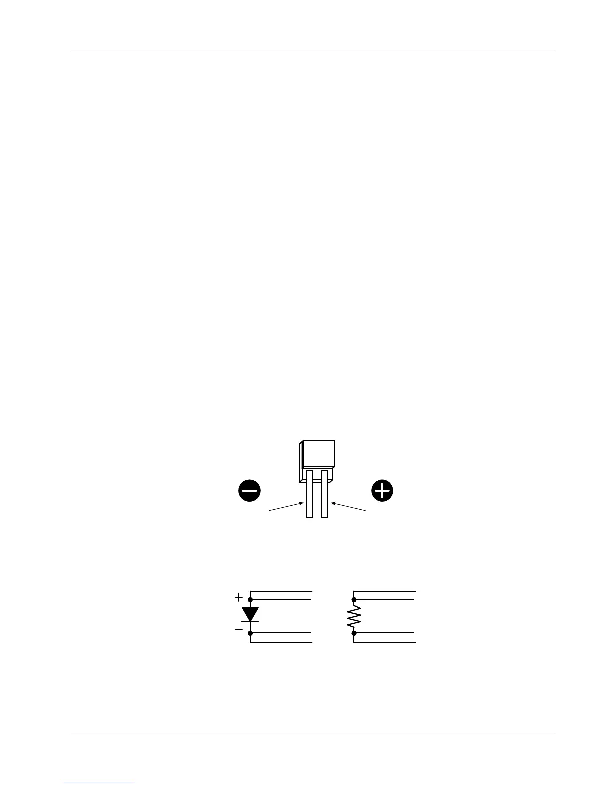
3.5.4 Sensor Polarity
Lake Shore sensors are shipped with instructions that indicate which sensor leads are which. It is
important to follow these instructions for plus and minus leads (polarity) as well as voltage and current
when applicable. Diode sensors do not operate in the wrong polarity. They look like an open circuit to
the instrument. Two lead resistors can operate with any lead arrangement and the sensor instructions
may not specify. Four-lead resistors can be more dependent on lead arrangement. Follow any
specified lead assignment for four lead resistors. Mixing leads could give a reading that appears
correct but is not the most accurate.
DT-470-SD
Diode Sensor Leads
Anode
Cathode
3.5.5 Four-Lead Sensor Measurement
All sensors, including both two-lead and four-lead, can be measured with a four-lead technique. The
purpose of a four-lead measurement is to eliminate the effect of lead resistance on the measurement.
If it is not taken out, lead resistance is a direct error when measuring a sensor.
I+
V+
I
V
Four-Lead
Diode
Four-Lead
Platinum
I+
V+
I
V
In a four-lead measurement, current leads and voltage leads are run separately up to the sensor.
With separate leads, there is little current in the voltage leads, so their resistance does not enter into
the measurement. Resistance in the current leads will not change the measurement as long as the
voltage compliance of the current source is not reached. When two-lead sensors are used in four-
lead measurements, the short leads on the sensor have an insignificant resistance.
Installation 3-5