Lake Shore Model 332 Temperature Controller User’s Manual
3.3 REAR PANEL DEFINITION
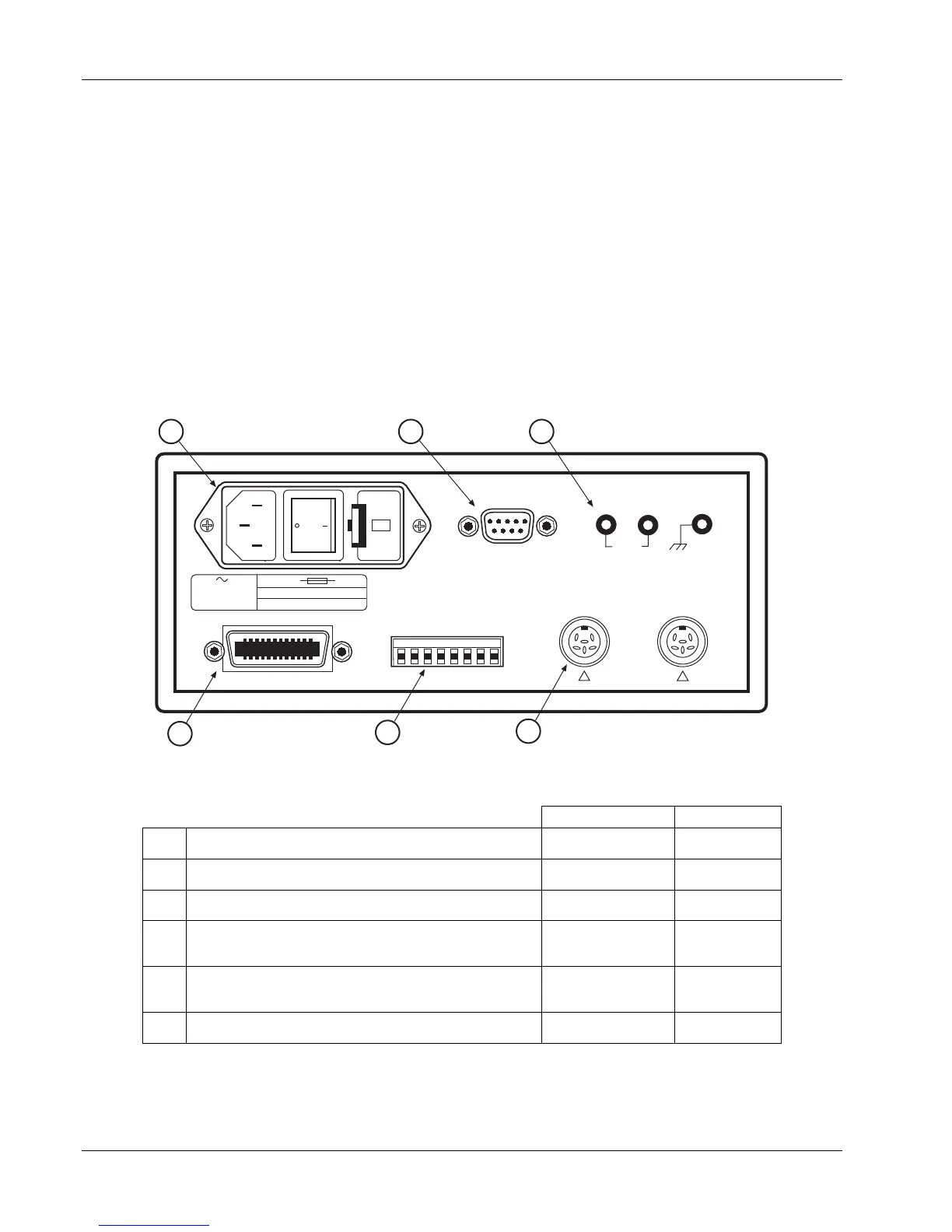
This paragraph provides a description of the Model 332 rear panel connections. The rear panel consists
of the line input assembly, RS-232 Connector, HEATER OUTPUT Connector, INPUT A and B Sensor
Input Connectors, the RELAY and ANALOG OUTPUT Terminal Block, and the IEEE-488 INTERFACE
Connector. Please read the entire chapter before performing the initial setup and system checkout
procedure in Paragraph 3.10. Rear panel connector pin-out details are provided in Paragraph 8.5.
CAUTION: Verify AC Line Voltage shown in the fuse holder window is appropriate for the intended
AC power input. Also remove and verify the proper fuse is installed before plugging in and
turning on the instrument.
CAUTION: Always turn off the instrument before making any rear panel connections. This is especially
critical when making sensor to instrument connections.
60V MAX60V MAX
120
RS-232 (DTE)
100/120V
220/240V
1.6 A T 250V
0.75 A T 250V
100/120/220/240 V
10% +6% Voltage
50-60 Hz 150 VA MAX
5×20mm
5×20mm
IEEE-488 INTERFACE
SH1 AH1 T5 L4 SR1 RL1 PP0 DC1 DT0 C0 E1
RELAYS 30VDC 5A
RELAY 1 RELAY 2
NC NO
+
ANALOG
OUTPUT
COM
NC NOCOM
HEATER OUTPUT
HI
LO
GND
1 2 3
4
5
6
INPUT A
I+
V+
I
V
INPUT B
I+
V+
I
V
NO USER SERVICEABLE PARTS
INSIDE. REFER SERVICING TO
TRAINED SERVICE PERSONNEL
WARNING
!
!
F-332-3-1.eps
Description Details
c
Line Input Assembly Paragraph 3.4 Figure 8-1
d
RS-232 (DTE) 9 pin D-Style Connector Paragraph 6.2.1 Figure 8-5
e
HEATER OUTPUT and Ground Banana Jacks Paragraph 3.7 Figure 8-3
f
INPUT A and INPUT B Sensor (or
Thermocouple) Input Connectors
Paragraphs 3.5
and 3.6
Figure 8-2
g
RELAYS and LOOP2/ANALOG OUTPUT
Terminal Block
Paragraphs 3.7,
3.8, and 3.9
Figure 8-4
h
IEEE-488 INTERFACE Connector Paragraph 8.4.2 Figure 8-6
Figure 3-1. Model 332 Rear Panel
3-2 Installation
 Loading...


