Lake Shore Model 332 Temperature Controller User’s Manual
8.7 LOOP 2 / ANALOG OUTPUT RANGE SELECTION
The loop 2 output / analog output may be configured to supply a maximum output of either 10 W or 1
W. The recommend setting for loop 2 is 10 W which supplies a maximum of 1 A through 10 Ω. This is
the factory default selection. The recommend setting for analog output is 1 W which supplies a
maximum of 100 mA through 100 Ω. The maximum output selection is determined by the position of
JMP 8. The location of JMP 8 is shown in Figure 8-7.
Use the following procedure to select the output range.
1. Follow the top of enclosure REMOVAL procedure in Paragraph 8.5.
2. Locate JMP 8 on the main circuit board. See Figure 8-7.
3. Move the jumper to the desired position, either 10 W or 1 W.
4. Follow the top of enclosure
INSTALLATION procedure in Paragraph 8.5.
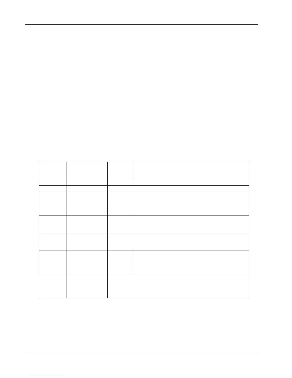
8.8 JUMPERS
There are seven jumpers located on the main circuit board of the Model 332. See Figure 8-7 for the
location of the jumpers (reference designators JMP1 thru JMP8).
CAUTION: Only JMP4, JMP7, and JMP8 should be changed by the user. Please consult
with Lake Shore before changing any of the other jumpers.
Reference
Designator
Silkscreen Default Description
JMP1 RUN / TEST RUN Used for diagnostic purposes only.
JMP2 RS-485 / RS-232 RS-232 Serial Interface mode. RS-485 is not supported.
JMP3 IEEE SHIELD Not Used Used for ground loop testing.
JMP4 330 / 340 330
Set at factory to reflect configuration of Input A
where 330 = 1 mA excitation current on Pin 3 of the
connector and 340 = Pin 3 connected to shield.
Refer to Paragraph 3.5.1.
JMP5 DI/RE / TC —
Set at factory to reflect configuration of Input A
where DI/RE = diode/resistor and TC =
thermocouple.
JMP6 DI/RE / TC —
Set at factory to reflect configuration of Input B
where DI/RE = diode/resistor and TC =
thermocouple.
JMP7 330 / 340 330
Set at factory to reflect configuration of Input B
where 330 = 1 mA excitation current on Pin 3 of the
connector and 340 = Pin 3 connected to shield.
Refer to Paragraph 3.5.1.
JMP8 1W / 10W 10W
Set at factory to select range of analog output / loop
2 heater output. 1W = maximum of 0.1 A through a
minimum load of 100 Ω. 10W = maximum of 1.0 A
though a minimum load of 10 Ω.
8-8 Service
 Loading...


