15
4 Design and Functions
4 Design and Functions
4.1 Design
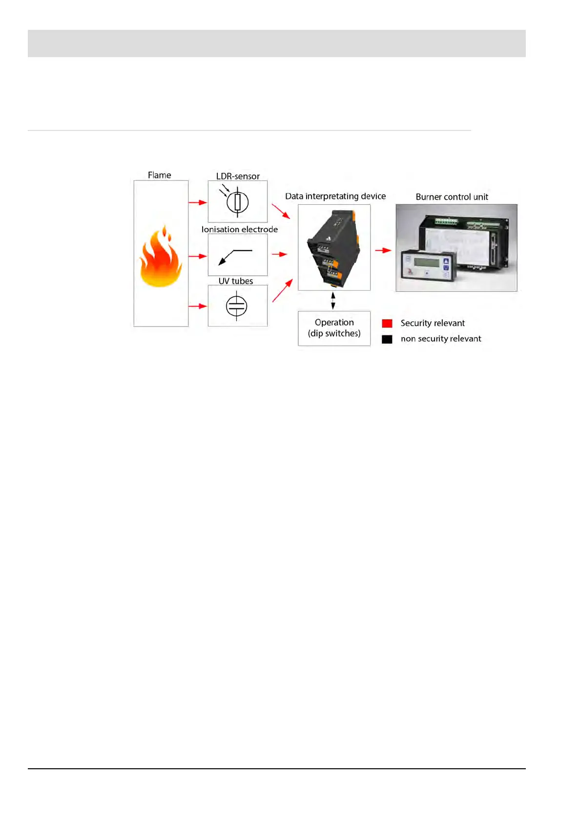
Fig. 4-1 Flame monitoring
The flame monitor consists of the F130l evaluation device and the flame sensors from chapter
4.2 Flame Sensors The F130l evaluation device is connected by pluggable screw terminals.
The following connection terminals are available:
• Supply of auxiliary power (mains voltage)
• Connection for LDR sensor
• Connection for ionisation electrode
• Connection for UV tubes
• Measurement output for ionisation current measurement
• 0/4..20mA analogue output for flame intensity
• Alarm relay output
• Flame signal output
The arrangement of the control and operating elements is shown in chapter 4.5 Control Ele-
ments.
The connection and terminal connection diagram can be found in chapter 11.2 Connecting Di-
agrams.