40
11 Appendix
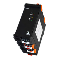
11.2.4 F130I terminal connection diagram
The sockets have a slot coding. This largely prevents the sockets from being swap.
Terminal Description of
terminal
PIN Description of PIN Coding
X23 FSB 1 FSB - Vcc 6
(currently no function)
2 FSB - GND
3 FSB - H
4 FSB - L
X13 Mains 1 - 0
2N
3 FPE
4L
X11 Störmeldung 1 Fault output 0
(potential-free) 2 Fault input
Flame signal 3 Flame input
(potential-free) 4 Flame output
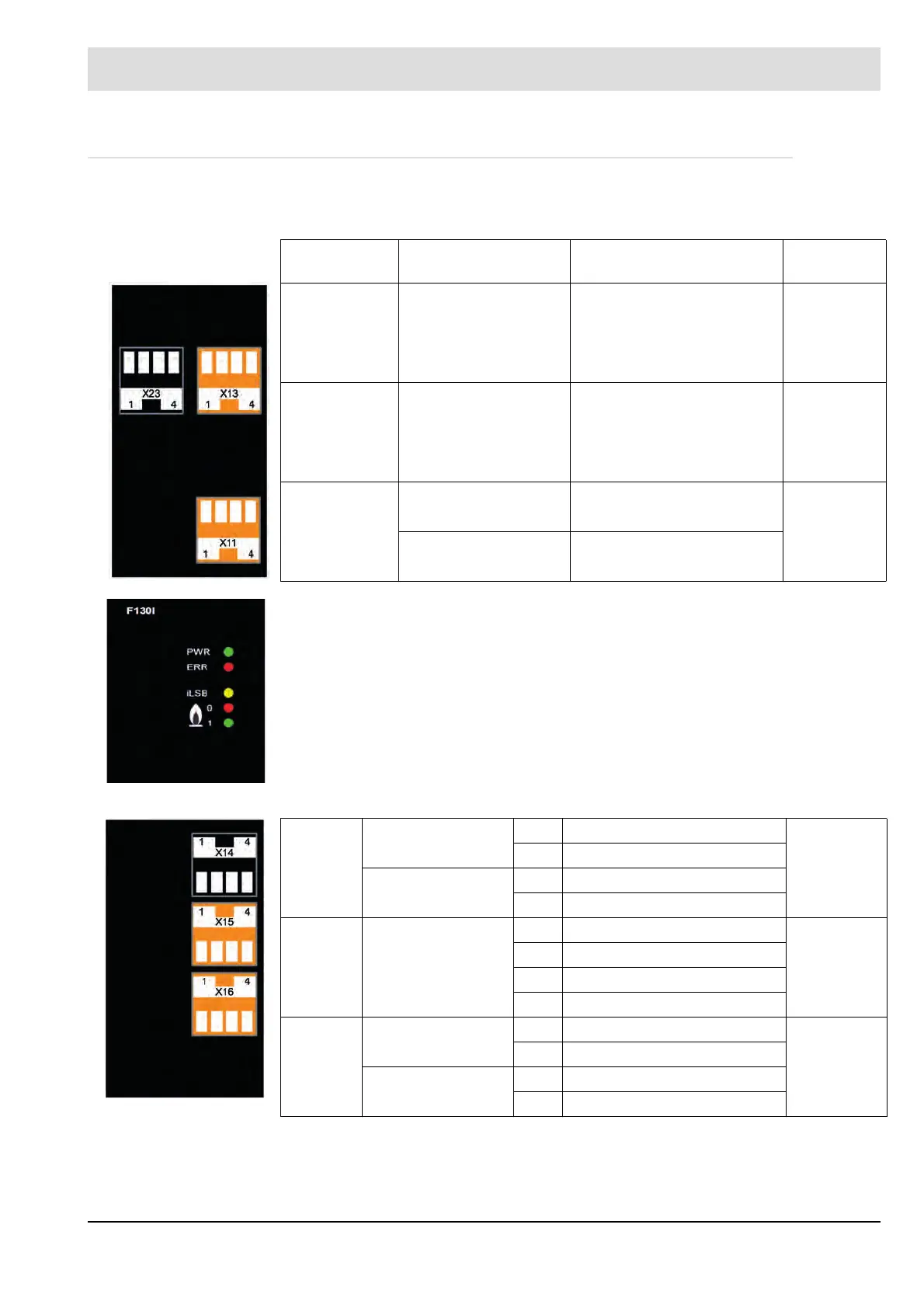
Operation
Problem
ILSB/FSB
Flame OFF
Flame ON
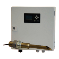
X14 Ionisation current 1 ION-Measuring - 6
2 ION-Measuring +
Current loop 3 0...20 mA -
4 0...20 mA +
X15 Ionisation input 1 ION-N 1
2 ION-L*
3 Supply Ionisation lance*
4 Ionisation lance
X16 UV-input 1 UV - 0
2 UV +
LDR-input 3 LDR +
4 LDR -