20
4 Design and Functions
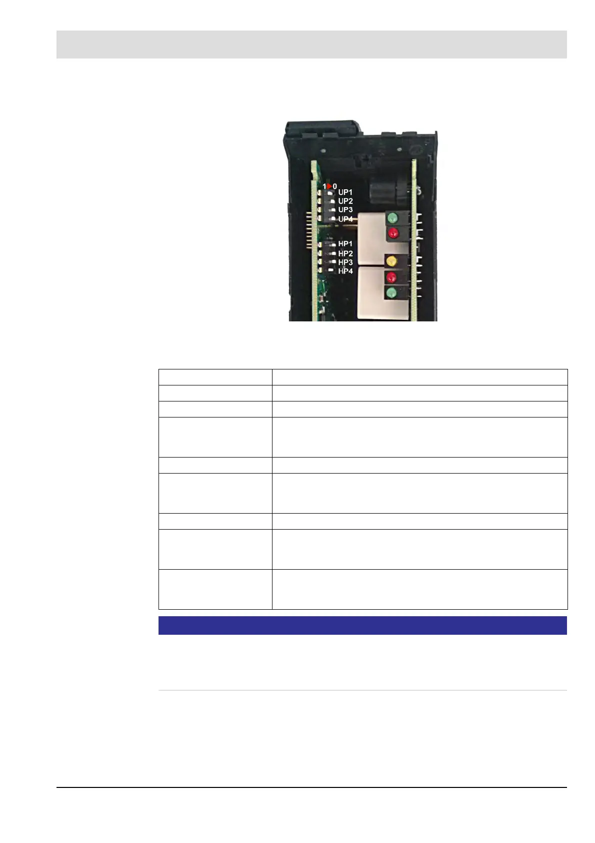
To activate the configuration switches UP1 to HP3, switch HP4 must be set to 1.
Fig. 4-3 DIP switches on the F130l
The following settings can be made using the configuration switches:
NOTICE
Set the FFDT parameters by a combination of HP3 and UP3 switches before commissioning.
The device must be disconnected from power while setting the parameters. Setting the FFDT
parameters during operation is not permitted. A non antivalent switch position causes a safety
shutdown. Follow the safety instructions in chapter 2
Switch no. Setting
UP 1 No Function
UP 2 free
UP 3 Selection FFDT
1 - FFDT 1 s in combination with HP 3 - 0
0 - FFDT 3 s in combination with HP 3 - 1
UP 4 free
HP 1 Mode current loop
1 - 4..20 mA active
0 - 0..20 mA active
HP 2 free
HP 3 Selection FFDT
0 - FFDT 1 s in combination with UP 3 - 1
1 - FFDT 3 s in combination with UP 3 - 0
HP 4 DIP switch enable
1 - DIP switch active/parametrisation via FSB inactive
0 - DIP switch inactive/parametrisation via FSB active