35
5 Commissioning
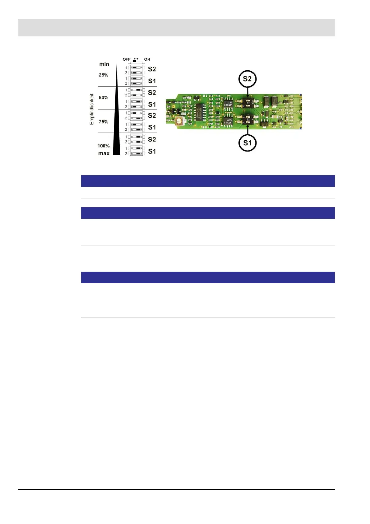
Fig. 5-5 DIP switches to modify the settings in FFS08
NOTICE
Both DIP switches (S1 and S2) must be set identically!
NOTICE
FFS08 UV does not offer the possibility for modifying sensitivity like the above mentioned. Op-
timisation can only be made by aligning the sensor with the monitored flame to an optimum
with the help of a measurable signal voltage at the measuring wire.
After successful setting, the printed circuit board is to be carefully inserted back into the hous-
ing and fastened to a stop.
NOTICE
When putting together housing and threaded cap, take note of an identification which prevents
a twist of optical lense on the housing and sensor on the printed circuit board. Only when the
identification is aligned, the threaded connection can be manually fastened and thereafter se-
curely fastened with tools.