Test Bed CoBox-Micro
2-6
Test Bed Connectors
The CoBox-Micro test bed has four connectors: CON1 (Serial Port 1 or Channel 1), CON2
(TTL Interface), CON4 (Serial Port 2 or Channel 2), and CON3, which is a 5VDC power
supply connector.
Note: CON3 is a PCB-mounted, center-positive 5VDC power supply
connector.
When J1 is closed, the input voltage required is 5 VDC (+ - 5%). When
open, input voltage is 6-9 VDC (nominal 6VDC). The 3-pin header
next to J1 is the second serial port.
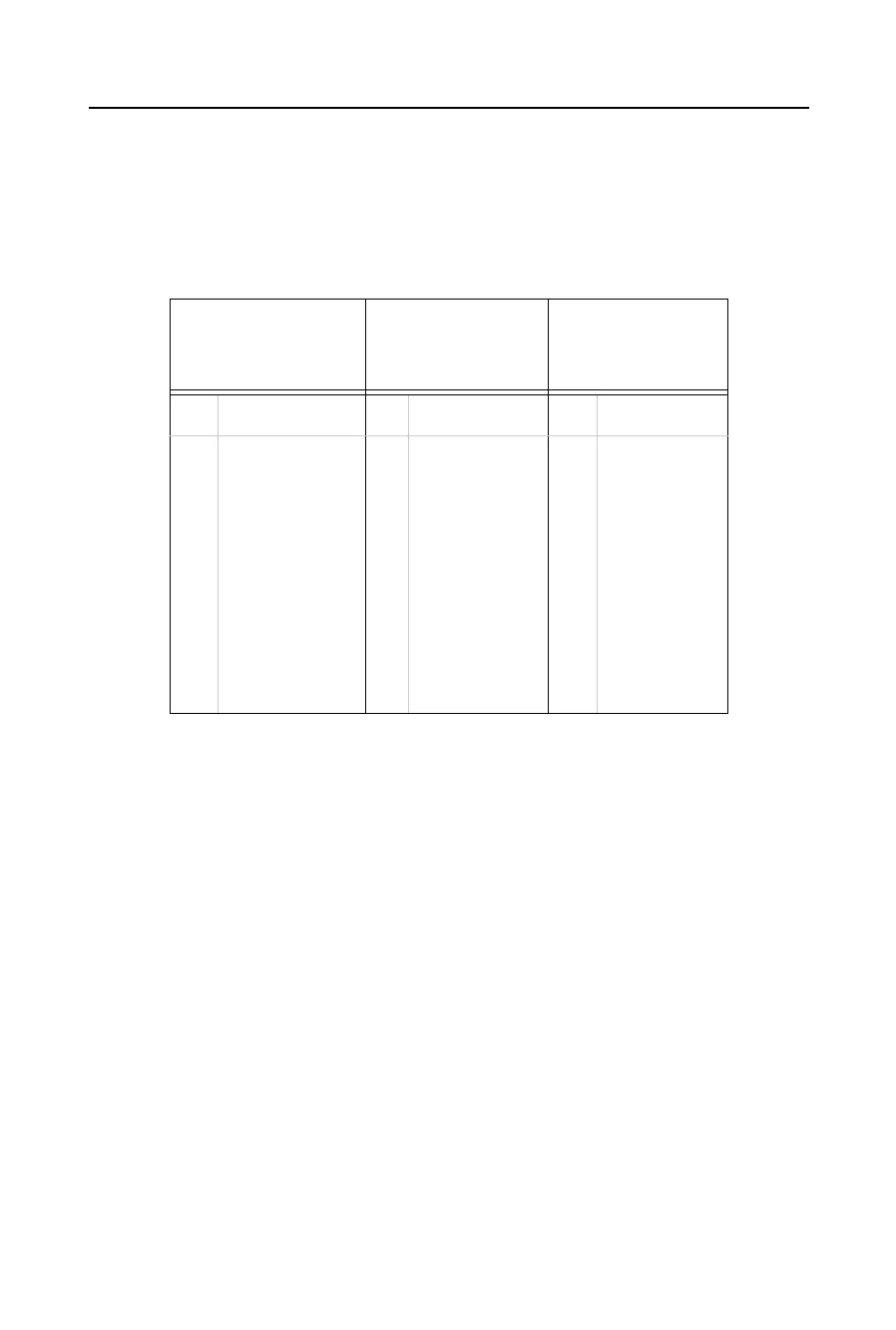
Table 2-3: CoBox-Micro Test Bed Connector Pinouts
CON1
Serial Port
(Channel) 1
a
a. “CON1 Serial Port (Channel) 1” is also designated as “A”.
CON2
TTL Interface
CON4
Serial Port
(Channel) 2
b
b. “CON4 Serial Port (Channel) 2” is also designated as “B”.
Pin Signal Pin Signal Pin Signal
1
2
3
4
5
6
7
8
9
DTRA (output)
TxA (output)
RxA (input)
DCDA (input)
GND
None
CTSA (input)
RTSA (output)
None
1
2
3
4
5
6
7
8
9
10
11
12
+5 VDC
GND
TxA (output)
RxA (input)
CTSA (input)
DCDA (input)
RTSA (output)
DTRA (output)
None
None
TxB (output)
RxB (input)
1
2
3
TxB (output)
RxB (input)
GND