CoBox-Mini Connectors
3-3
Contact Lantronix or visit our Web site (www.lantronix.com) for information about
ordering Device Servers with various connector configurations.
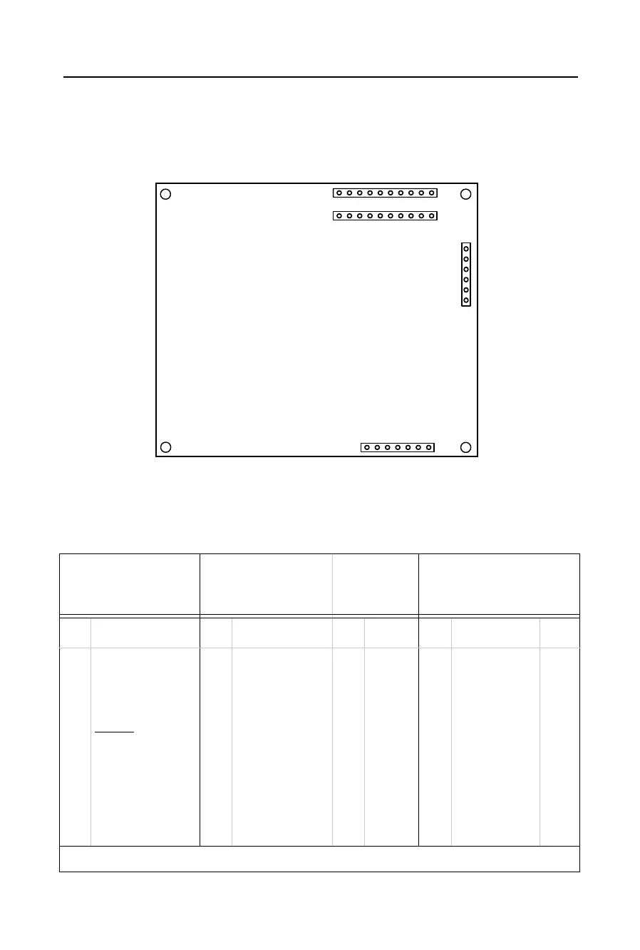
Figure 3-2: CoBox-Mini Connector Layout
The Embedded Integration Kit includes the CoBox-Mini embedded device server. Refer to
the following table for a listing of its pinouts.
Table 3-1: CoBox-Mini Connector Pinouts
CON1
TTL Serial Port
CON4
TTL Serial Port with
Full Handshaking
CON2
AUI
Connector
CON3
10BASE-T Connector
Pin Signal Pin Signal Pin Signal Pin Signal RJ45
1
2
3
4
5
6
7
8
9
10
+5VDC
GND
TxA (output)
RxA (input)
RESET
(pull low
to reset)
DCDA (input)
LED1 (Channel 1)
LED2 (Channel 2)
LED3 (Diagnostic)
+5VDC (for LEDs)
1
2
3
4
5
6
7
8
9
10
DTRA (output)
GND
RxB (input)
TxB (output)
CTSA (input)
CTSB (input)
RTSA (output)
DTRB (output)
DCDB (input)
RTSB (output)
1
2
3
4
5
6
CD+
CD-
Rx+
Rx-
Tx+
Tx-
1
2
3
4
5
6
7
Tx+
Tx-
Rx+
Rx-
None
LED 4 (Link)
+5VDC (LED)
1
2
3
6
A = Port (Channel) 1 B = Port (Channel) 2
CON1
1
1
1
17
6
10
CON4
CON2
CON3
 Loading...