LAUNCH CreaderV User’s Manual
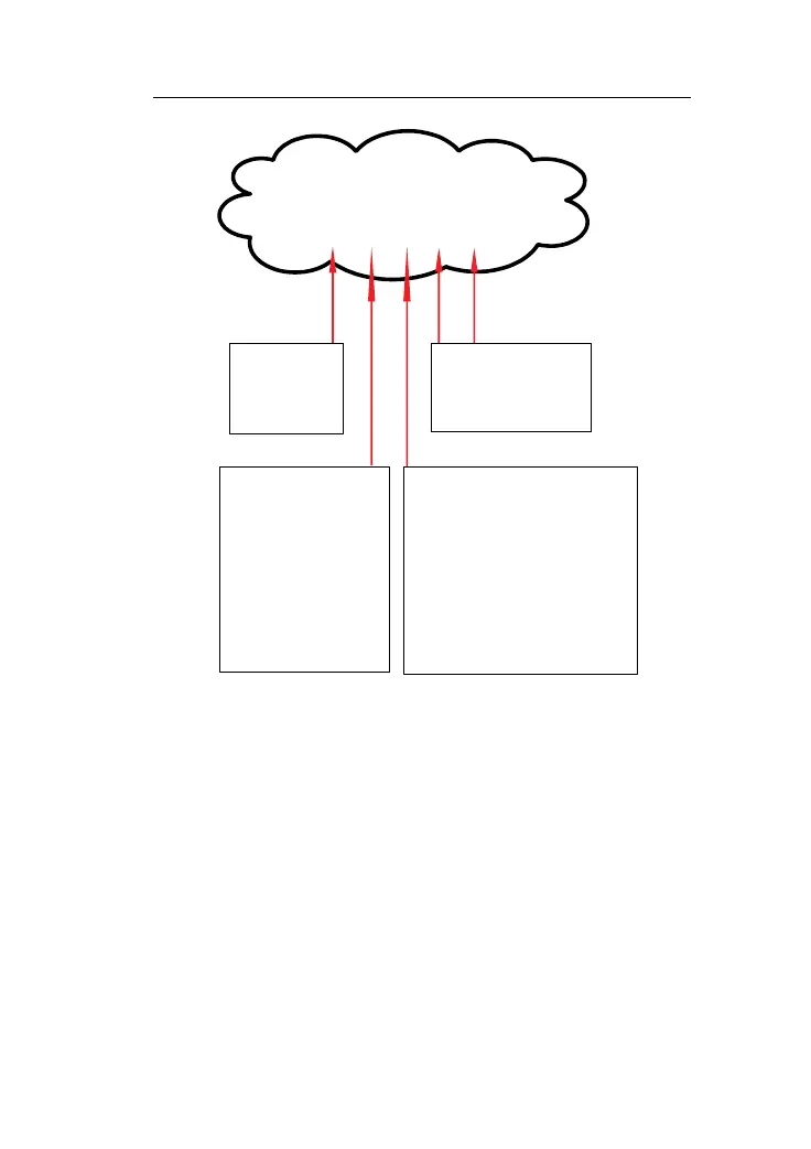
DTC Example
P 0 2 0 2
Identifying specific
malfunctioning section
of the systems
Systems
P=Powrtrain
B=Body
C=Chassis
U=Network
Code Type
Generic(SAE)
P0,P2,P34-P39
B0,B3
C0,C3
U0,U3
Manufacturer Specific:
P1,P30-P33
B1,B2
C1,C2
U1,U2
Sub-systems
1=Fuel and air metering
2=Fuel and air metering
3=Ignition system or misfire
4=Auxiliary emission controls
5=Vehicle speed,idle control, and
auxiliary inputs
6=Computer and auxiliary outputs
7=Transmission
8=Transmission
9=Transmission
2.3 Location of the Data Link Connector (DLC)
The DLC (Data Link Connector or Diagnostic Link Connector) is the
standardized 16-cavity connector where diagnostic code readers
interface with the vehicle's on-board computer. The DLC is usually
located 12 inches from the center of the instrument panel (dash), under
or around the driver’s side for most vehicles. If Data Link Connector is
not located under dashboard, a label should be there telling location. For
5