31
ENGLISH
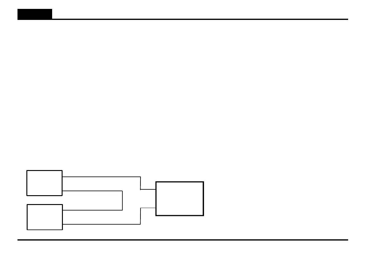
L) CONNECTION FOR BUFFER BATTERY
The unit CTR50 can be used to control 24Vdc motors with or without buffer battery. The battery charger is included in the card.
WARNING: Compulsively respect the connection diagram for the buffer battery here below. Cards with damaged components will not be held as
in guarantee if the damage comes from a wrong positioning of the jumper JP2 or from an incorrect wiring.
12V
12V
FS1
-
+
CTR50
-
+
-
+
FS2
I) QUICK GUIDE TO INSTALLATION
Once you have run the wiring, perform sequentially the following procedure:
1. Single wing installation: Make sure that the operator is connected in terminal board J1 to terminals 7-8 (M2) and that the
DIP 5=ON;
2 wings installation: make sure that the motor delayed in closing is connected in terminal board J1 to terminals 7-8 (M2) and
that the DIP 5=off if you wish to get a phase displacement between the wings;
2. Connect to main electric power 230 Vac the unit;
3. Store at least 1 remote control (page 27).
WARNING: If there is no stop button, insert a jumper between the terminals 4-5 in terminal board J2;
4. Check correct polarity of the connected motors. Manually release the operators and place the wings at half stroke. Lock the operators.
Give the start command with the remote control and check an opening motion starts. Otherwise reverse the closing motors connection;
5. If the gate doesn’t start, check the connections of safety devices and possibly put jumpers on all contacts NC (normally closed) and try
a g a i n .
6. Carry on programming by referring to the instructions in paragraph G) of this manual.
7. Set the required working logic (page 24), programme pause time and delays between wings if needed (page 29-30
intervention of amperometric sensor with RV1, and other possible customizations.
WARNING: Make sure the jumper JP2 is correctly
inserted between the terminals 2 - 3