CS10/CS15 & GS Sensors, Operation
37
4.1.4 Setting up Viva Uno
Use The equipment setups described following are to be used for static operations over
markers or for rover with extended periods of use in the field.
Description The Viva Uno instrument consists of the CS field controller (CS10/CS15) and the GS
GNSS antenna cap (GS05/GS06) attached to the CS field controller.
The CS field controller with the GS GNSS antenna cap attached, clips to the tripod leg.
Connections are made to the external GNSS antenna.
The CS field controller with the GS GNSS antenna cap attached is fixed to the pole with
the GHT62. The setup can be used as a DGPS rover, if fitted with the DGPS option.
• GNSS antenna is mounted directly using screw fitting. If using stub and adapter,
procedures can vary slightly.
• When using the adapter and carrier, ensure that the GNSS antenna and the adapter
assembly slide down the full length of the carrier stub. An incorrectly mounted
GNSS antenna will have a direct effect on the results.
• GNSS antenna is AS05.
If the instrument is left in the container during use in high temperatures, the lid should
be left open. Refer to the CS10/CS15 User Manual for operating and storage temper-
atures.
It is always recommended to use the external GNSS antenna (AS05) to optimise the
reception of satellite signals.
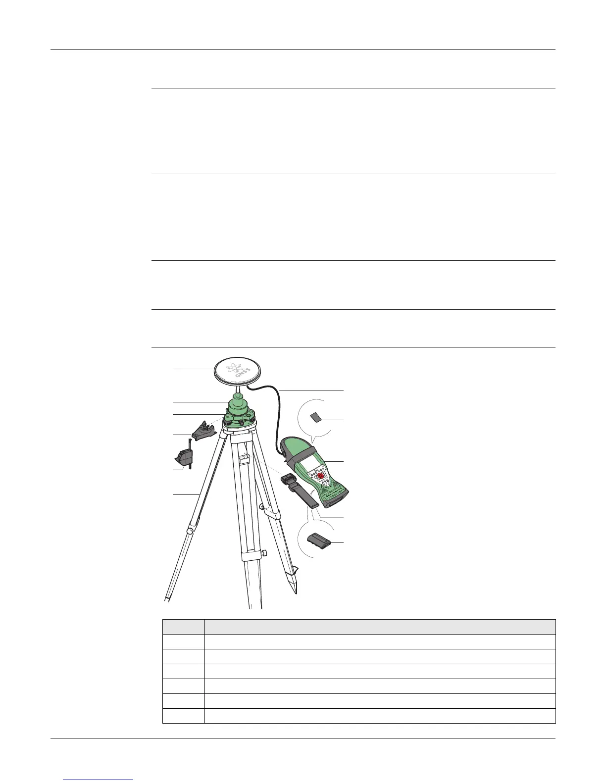
Viva Uno tripod
setup
a) GNSS antenna AS05
b) GRT146 carrier
c) Tribrach
d) GHT196 tribrach bracket for height
meter
e) GHM007 instrument height meter
f) Tripod
g) 1.2 m antenna cable
h) SD card
i) Viva Uno instrument (CS field controller
with GNSS cap)
j) GHT61 hand strap
k) GEB211/GEB212 battery
Step Description
1. Set up the tripod.
2. Mount and level the tribrach on the tripod.
3. Ensure that the tribrach is over the marker.
4. Place and lock the carrier in the tribrach.
5. Screw the GNSS antenna onto the carrier.
6. Check that the tribrach is still level.
a
b
c
d
e
f
g
i
k
j
0012600_001
h