CS10/CS15 & GS Sensors, Pin Assignments and Sockets
71
Appendix A Pin Assignments and Sockets
A.1 CS10/CS15
Description Some applications require knowledge of the pin assignments for the instrument ports.
In this chapter, the pin assignments and sockets for the instrument ports are
explained.
Ports at the
instrument bottom
panel - DSUB9
connector
Ports at the
instrument bottom
panel - Lemo
connector
Pin assignments for
RS232 serial port
Pin assignments for
8pin LEMO-1
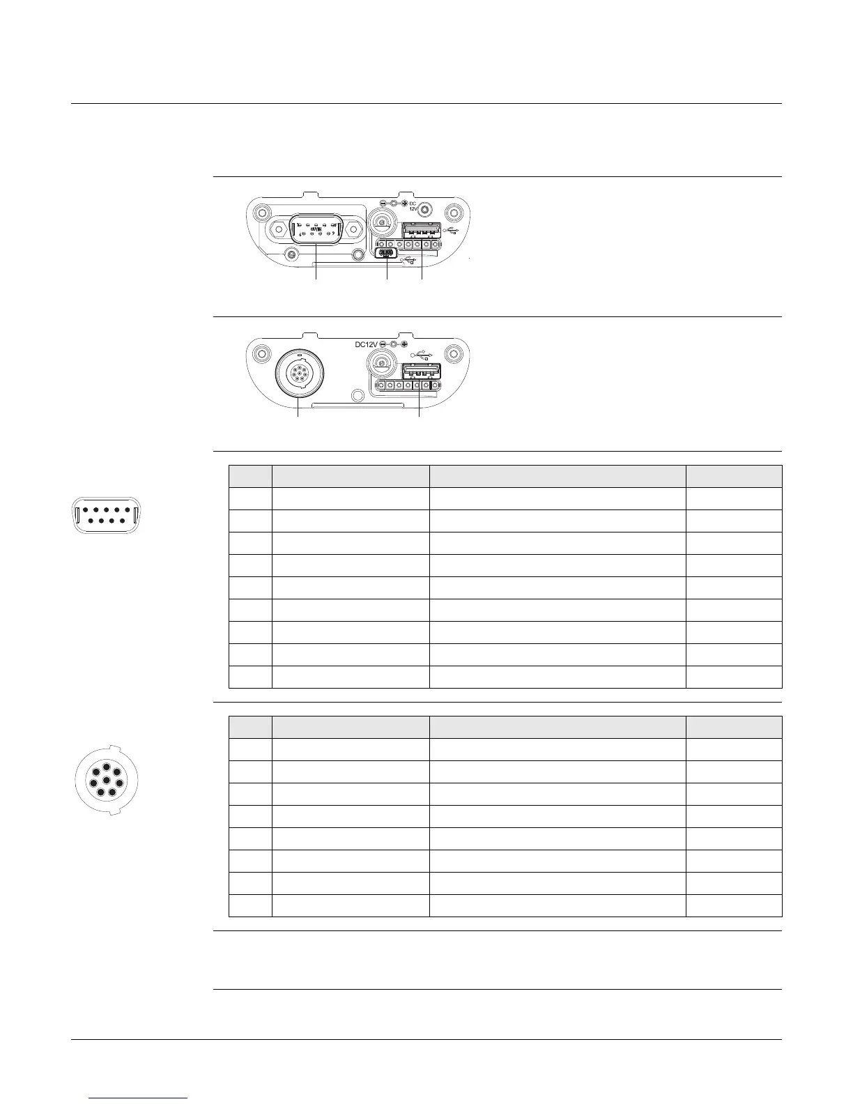
Sockets
a) DSUB9 port
b) USB Mini port
c) USB A Host port
CS_022
a b c
a) Lemo port (USB and serial)
b) USB A Host port
CS_021
a b
PIN_002
1
6789
2345
Pin Signal Name Function Direction
1NC Not connected -
2 RxD RS232, receive data In
3 TxD RS232, transmit data Out
4NC Not connected -
5GND Signal Ground -
6NC Not connected -
7 RTS RS232, request to send Out
8 CTS RS232, clear to send In
9NC Not connected -
1
7
6
8
5
4
3
2
PIN_001
Pin Signal Name Function Direction
1 USB_D+ USB data line In or out
2 USB_D- USB data line In or out
3GND Signal ground -
4 RxD RS232, receive data In
5 TxD RS232, transmit data Out
6 ID Identification pin In or out
7 PWR Power input, 10.5V-28V In
8 TRM_ON/USB_ID RS232, general purpose signal In or out
9 pin RS232: RS232, 9 pin, DB9
8 pin LEMO-1: LEMO-1, 8 pin, LEMO EGI.1B.308.CLN