Page 16
CBX40UHV
IMPORTANT
Before changing any clippable links or jumper settings,
make sure the motor has completely stopped. Any
changes will not take place while the motor is running.
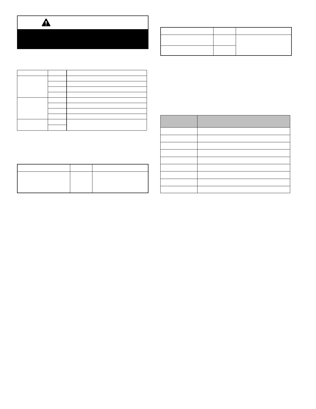
Table 3. Air Handler Control Connections —
Communicating (CBX40UHV-XXX-230-6-ALL)
Label Label Function
Thermostat
R 24VAC
i+ RSbus data high connection
i- RSbus data low connection
C 24VAC command (ground)
Outdoor Unit
R 24VAC
i+ RSbus data high connection
i- RSbus data low connection
C 24VAC command (ground)
Link
i+
Not used.
i-
Thermostat Wire Length
Table 4. Run Length — Communicating
(CBX40UHV-XXX-230-6-02)
Wire Run Length AWG # Insulation/Core Types
Maximum length of wiring
for all connections on the
RSBus is limited to 1500
feet (457 meters).
18
Color-coded, temperature
rating 95
º
F (35
º
C) minimum,
solid core. (Class II Rated
Wiring)
Table 5. Run Length — Non-Communicating
(CBX40UHV-XXX-230-6-01 and -02)
Wire Run Length AWG # Insulation/Core Types
Less than 100' (30m) 18
Color-coded, temperature
rating 95
º
F (35
º
C) minimum,
solid core. (Class II Rated
Wiring)
More than 100' (30m) 16
Air Handler Control 9-Pin Connector
1. Air Handler ONLY - 2-wire harness (Wired to points 7
and 8) from the factory provides 230 volt power to Air
Handler Control.
2. Air Handler with ECB40 Electric Heat - 8-wire harness
(Wired as noted in table 6)
NOTE - See Figure 4
Table 6. Stages
Position &
Wire Color
Function / Description
1 red Heat stage 1 relay coil
2 orange Heat stage 2 relay coil
3 yellow Relay coil return
4 black Heat stage 3 relay coil
5 brown Heat stage 4 relay coil
6 blue Heat stage 5 relay coil
7 black L1 230VAC supply from heater kit
8 red L2 230 VAC supply from heater kit
9 Not Used

 Loading...


