Page 9
CBX40UHV
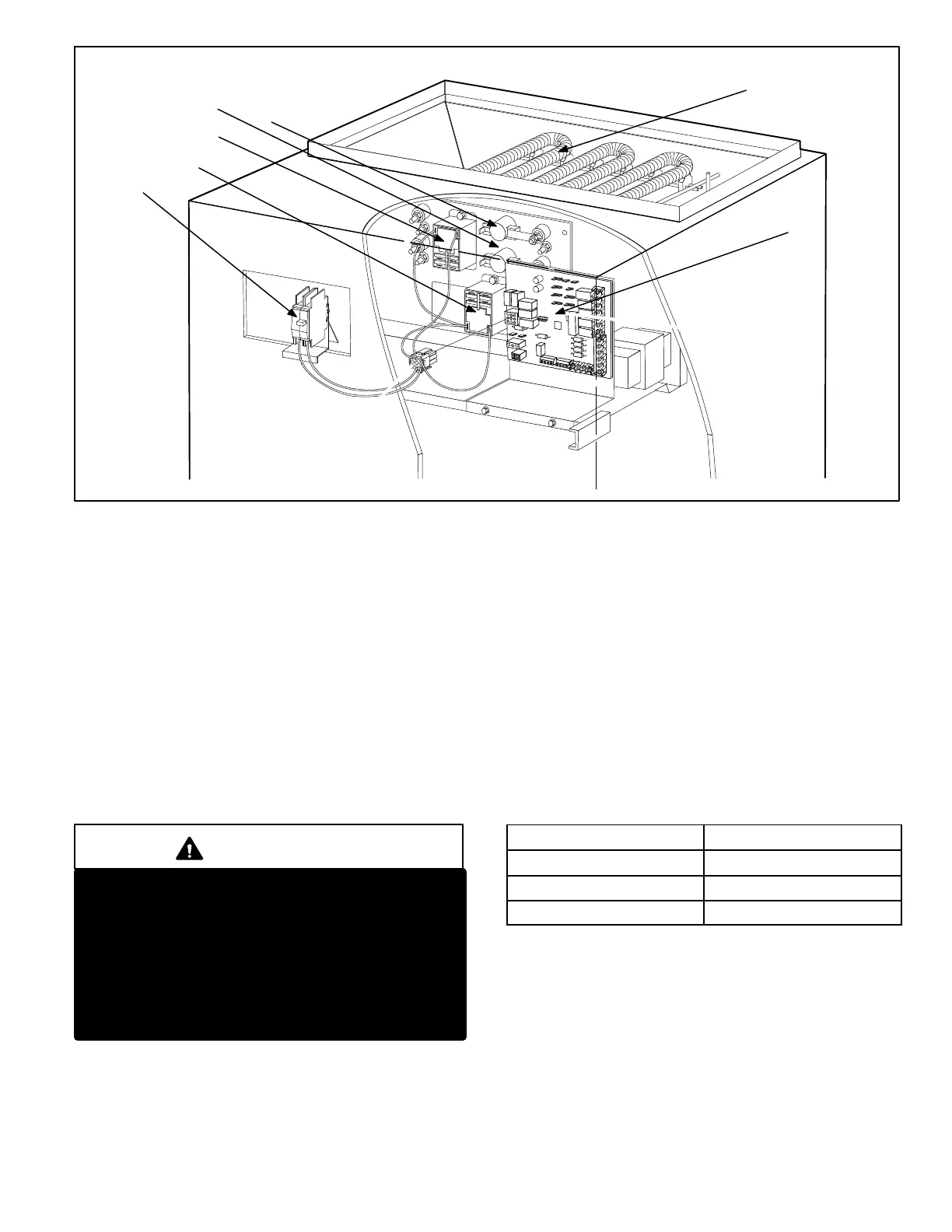
HEATING ELEMENTSHEATING ELEMENTS
CIRCUIT BREAKER
AIR HANDLER CONTROL
RELAY
RELAY
LIMIT
LIMIT
Figure 2. CBX40UHV Control Box
APPLICATION
CBX40UHV air handlers are designed for HFC-410A
applications only. All major air handler components
must be matched according to Lennox
recommendations for the unit to be covered under
warranty. Refer to the Engineering Handbook for approved
system matchups. A misapplied system will cause erratic
operation and can result in early unit failure. The units come
with factory installed check and expansion valve for all
applications. It has been installed internally and is accessible if
required.
ELECTROSTATIC DISCHARGE (ESD)
PRECAUTIONS AND PROCEDURES
CAUTION
Electrostatic discharge can affect electronic compo
nents. Take precautions during unit installation and
service to protect the unit's electronic controls. Pre
cautions will help to avoid control exposure to electro
static discharge by putting the unit, the control and the
technician at the same electrostatic potential.
Neutralize electrostatic charge by touching hand and
all tools on an unpainted unit surface before perform
ing any service procedure.
UNIT COMPONENTS
Control Box
The CBX40UHV control box is shown in figure 2. Line
voltage and electric heat connections are made in the
control box. Optional electric heat fits through an opening
located in the center of the control box. When electric heat
is not used, knockout plates cover the opening. The electric
heat control arrangement is detailed in the electric heat section
of this manual.
Low voltage connections are made on the air handler
control (AHC) also located in the control box. All AHC will
have factory installed clippable links connecting DS to R, R
to O and Y1 to Y2. These links will have to be removed in
certain unit application. See table 1.
Table 1. Links
Application
Remove Links
Harmony IIIt DS to R
Heat Pump R to O
Two-Stage Cooling Y1 to Y2
Transformer (T1)
All CBX40UHV series units use a single line voltage to
24VAC transformer mounted in the control box. The
transformer supplies power to the control circuits in the
indoor and outdoor unit. Transformers are rated at 70VA.
208/240VAC single‐phase transformers use two primary
voltage taps.

 Loading...


