Page 43
CBX40UHV
CONFIGURING UNIT FLOW CHARTS
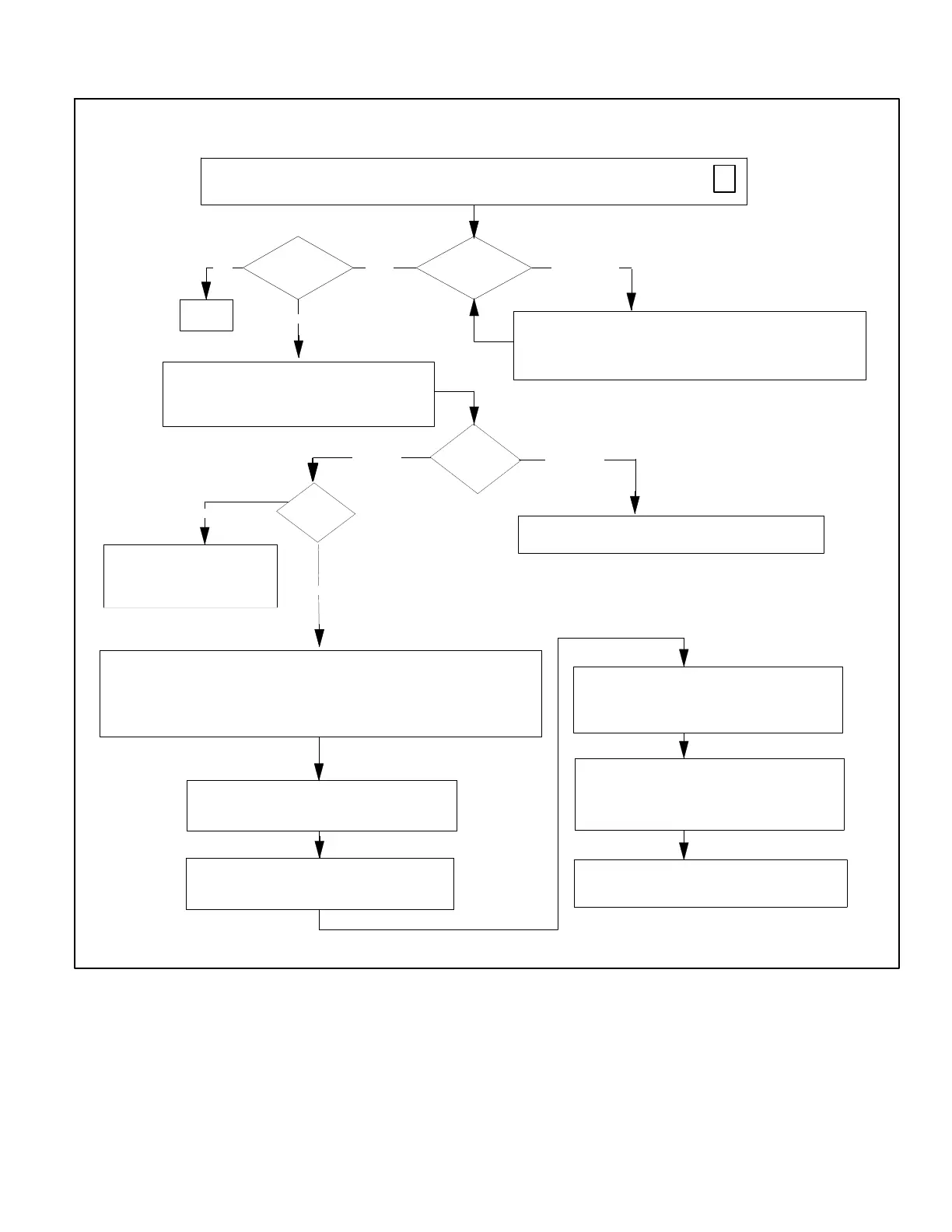
1. Air Handler Control (AHC) Checkout
Air Handler Control Checkout
Power-up — Unit Size Code (Number or letter) displayed represents air handler model size and capacity. If
three horizontal bars displays, Air Handler Control (AHC) does not recognize unit size code (air handler
model size and capacity).
AHC recognizes
Unit Size Code?
Electric heat
Installed?
Finished
Which Heat
Mode?
Refer to EVENHEAT Operation flow diagram, Air Handler or
ECB40 Electric Heat installation instructions.
W1 Call?
YesNo
Yes
No (Display
Alarm Code
203)
Standard
EVENHEAT
Refer to Heat Pump or Cooling
Sequence of Operation flow
diagrams, Air Handler or ECB40
Electric Heat installation
instructions.
A call for electric heating first, second or third stage is
initiated when 24 VAC (R) is detected on W1, W2 and W3
inputs on AHC. (Factory mounted metal jumpers connect
W1/2 and W2/W3.)
At the completion of each heat section demand (W1,
W2, and W3), the AHC will immediately de-energize the
corresponding pilot relay(s).
At the completion of all heating demands, the indoor
blower will run for an additional 10 seconds before
de-energizing.
No
Yes
NOTE - If the call for lower heat section is removed, AHC
will automatically de-energize higher heat sections.
Indoor blower will immediately start to delivery CFM as
set by heating mode jumper on AHC with activation of
first electric heat pilot relay.
Pilot relays on AHC are energized one at a time. There
is a minimum of 10 seconds delay between pilot relay
activations.
After all electric heat installations, AHC must be
manually configured to detect number of heat sections.
Refer to Configuring/Detecting electric heat sections
flow diagram, Air Handler or ECB40 Electric Heat
installation
IMPORTANT — Field replacement AHC may need to be manually
configured to validate air handler unit size code.
Refer to Configuring Unit Size Codes flow diagram, Air Handler or
ECB40 Electric Heat installation instructions.
ONE (H1)
H1
TWO (H1-H2)
H1
H2
H2
THREE (H1-H3)
H1
H2
H3
FOUR (H1-H4)
H1 AND H2
H3
H4
FIVE (H1-H5)
H1 AND H2
H3 AND H4
H5
T-STAT CALL
W1
W2
W3
NUMBER OF HEAT SECTIONS DETECTED
NOTE — AHC will not recognize higher heat sections
calls if lower heat section is not present.
RECOMMEND — USE FIGURE 12 AS A REFERENCE FOR SETTING JUMPER CONFIGURATIONS ON THE AIR HANDLER CONTROL.
Figure 33. Air Handler Control Checkout

 Loading...


