Page 41
CBX40UHV
START‐UP - OPERATION
Preliminary and Seasonal Checks
1. Make sure the unit is installed in accordance with the
installation instructions.
2. Inspect electrical wiring, both field and factory installed for
loose connections. Tighten as required.
3. Check voltage at disconnect switch. Voltage must be
within range listed on the nameplate. If not, consult the
power company and have voltage condition
corrected before starting unit.
4. Check to ensure that refrigerant lines are in good
condition and pipe insulation is intact.
5. Inspect condition of condensate drain pan and piping
assembly. Disassemble and clean seasonally.
Cooling Start‐Up
NOTE — The following is a generalized procedure and
does not apply to all thermostat control systems. Electronic
thermostat control systems may operate differently.
1. Set fan switch to AUTO or ON and move the system
selection switch to COOL. Adjust the thermostat to a
setting far enough below room temperature to bring on the
compressor. Compressor will start and cycle on demand
from the thermostat.
2. The refrigerant circuit is charged with HFC-410A
refrigerant. See condensing unit rating plate for
correct charge amount.
3. Refer to the correct condensing unit service manual for
more information.
Heating Start‐Up
1. Set the fan switch to AUTO or ON and move the
system selection switch to HEAT. Adjust the
thermostat setting above room temperature.
2. The indoor blower immediately starts and the electric heat
will stage on based on sequence timing.
Safety or Emergency Shutdown
Turn off unit power at circuit breaker.
Extended Period Shutdown
Turn off thermostat or set to UNOCCUPIED mode. Turn off
power to unit. All access panels and covers must be in place
and secured. The condensate assembly should be clean
and dry for extended period shutdown.
OPERATING CHARACTERISTICS
Blower Operation and Adjustment
NOTE — The following is a generalized procedure and
does not apply to all thermostat controls.
1. Blower operation is dependent on thermostat
control system.
2. Generally, blower operation is set at thermostat
subbase fan switch. With fan switch in ON position,
blower operates continuously. With fan switch in AUTO
position, blower cycles with demand.
3. In all cases, blower and entire unit will be off when the
system switch is in OFF position.
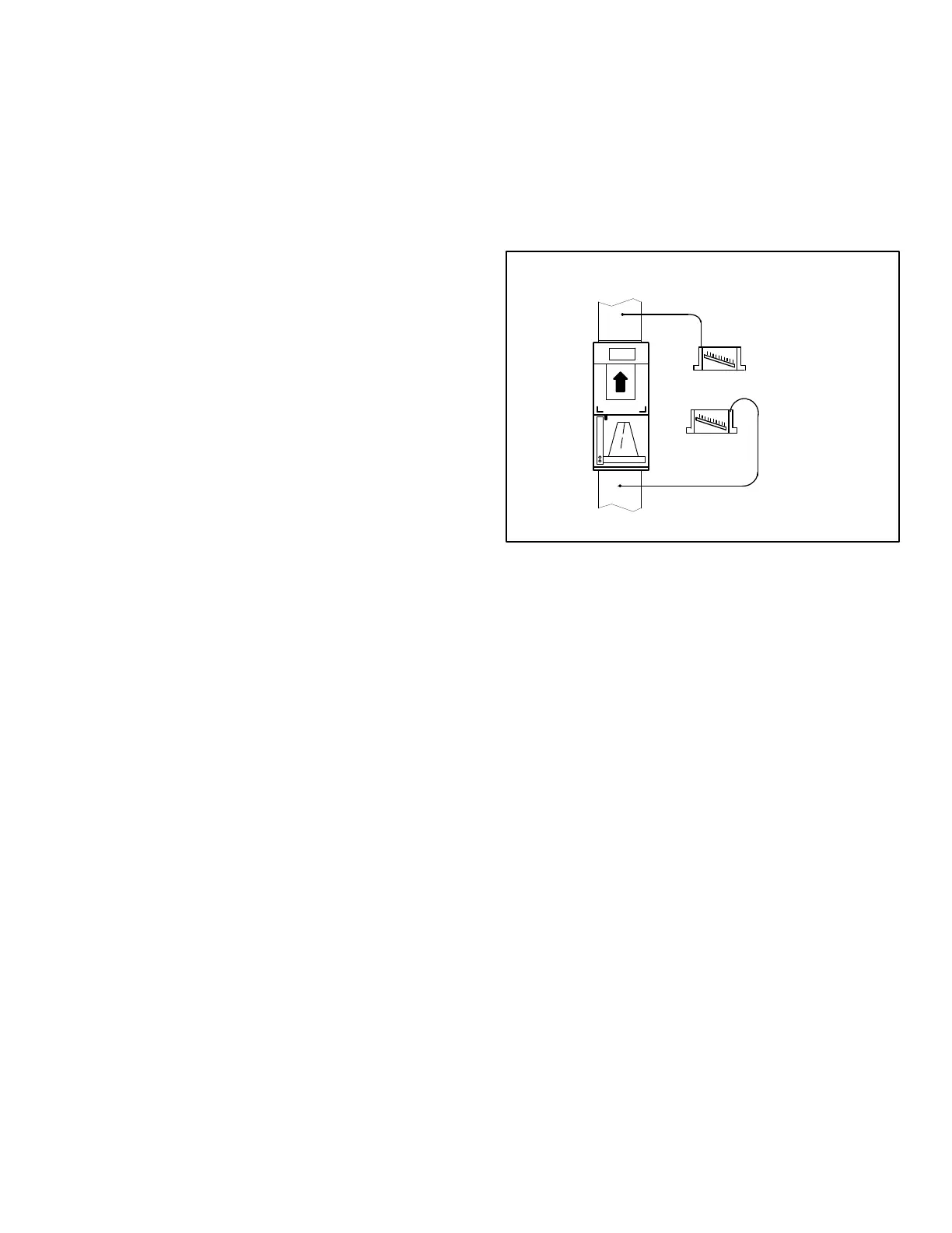
External Static Pressure
Measure tap locations as shown in figure 31.
MANOMETER
SUPPLY
RETURN
UNIT SHOWN IN
Up-Flow POSITION
+
_
Figure 31. Static Pressure Test
4. Punch a 1/4” (6mm) diameter hole in supply and return
air plenums. Insert manometer hose flush with inside
edge of hole or insulation in the supply plenum only. Seal
around the hose with permagum. Connect the other end
of the hose to the zero end of the manometer. Leave the
other end of the manometer open to the atmosphere.
5. With only the blower motor running and the
evaporator coil dry, observe and take note of the
manometer reading.
6. Repeat step 2 for the return air plenum. Insert
manometer hose to the opposite end of the zero side
of the manometer. Leave the zero side of the
manometer open to atmosphere.
7. Repeat step 3.
8. Add the absolute values of the supply air reading and
the return air reading to get the external static pressure
of the unit. For example -.20 in. wg. on the return and
+.30 in. wg. on the supply result in external static
pressure of .50 in. wg. External static should not
exceed .80” w.g. (200Pa)
Adjust blower motor speed to deliver the air desired
according to job requirements.
9. Seal around the holes when the check is complete.

 Loading...


