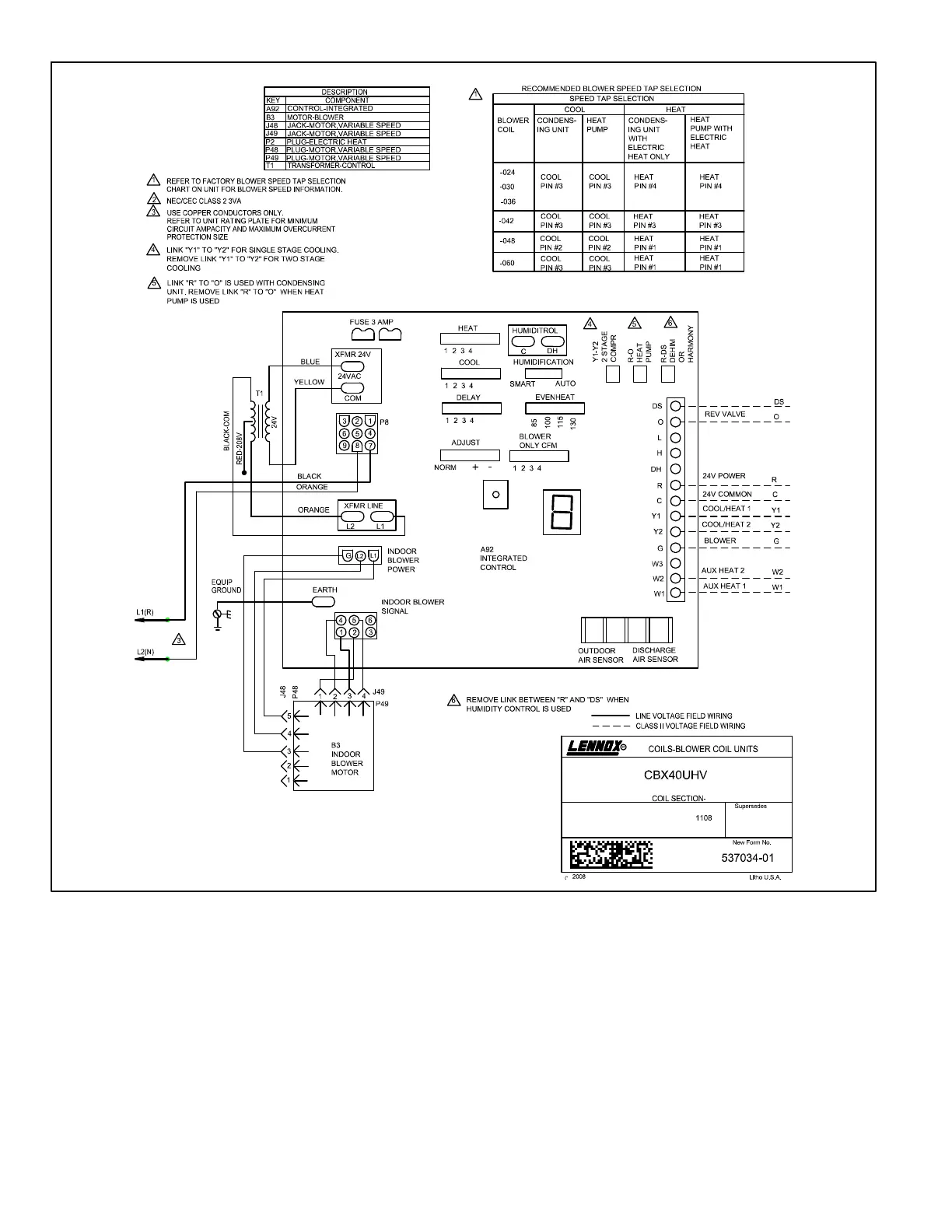
EasyManuals Logo

Lennox CBX40UHV Series User Manual

Lennox CBX40UHV Series
61 pages
To Next Page IconTo Next Page
To Previous Page IconTo Previous Page
Page #52 background imageLoading...
Page #52 background image
Page 52
CBX40UHV
UNIT DIAGRAM
CBX40UHV - 208/230V SINGLE PHASE - SEQUENCE OF OPERATION
1. Line voltage is routed to transformer T1 and blower motor B3.
2. T1 supplies 24VAC to terminal strip TB2, which supplies 24VAC to the indoor thermostat and electric heat, if used.
HEATING
3. W1 of the thermostat provides a W1 demand to the AHC. The AHC outputs a 22VDC signal to the K32 relay contained
in the ECB40 heat section. (See electric heat diagrams for operation).
4. AHC energizes blower motor B3 on heating speed.

Table of Contents

Other manuals for Lennox CBX40UHV Series

Questions and Answers:

Question and Answer IconNeed help?

Do you have a question about the Lennox CBX40UHV Series and is the answer not in the manual?

Lennox CBX40UHV Series Specifications

General IconGeneral
BrandLennox
ModelCBX40UHV Series
CategoryAir Handlers
LanguageEnglish

Related product manuals