Page 40
CBX40UHV
cabinet is supported. Use securing screws no longer
than 1/2” (12.7mm) to avoid damage to coil or filter as
illustrated in figure 27. Connect return and supply air
plenums as required using sheet metal screws.
Condensate Drain
LEFT-HAND AIR
DISCHARGE
MAIN DRAIN ON
RIGHT
OVERFLOW
DRAIN ON LEFT
UPFLOW OR
DOWNFLOW
RIGHT-HAND AIR
DISCHARGE
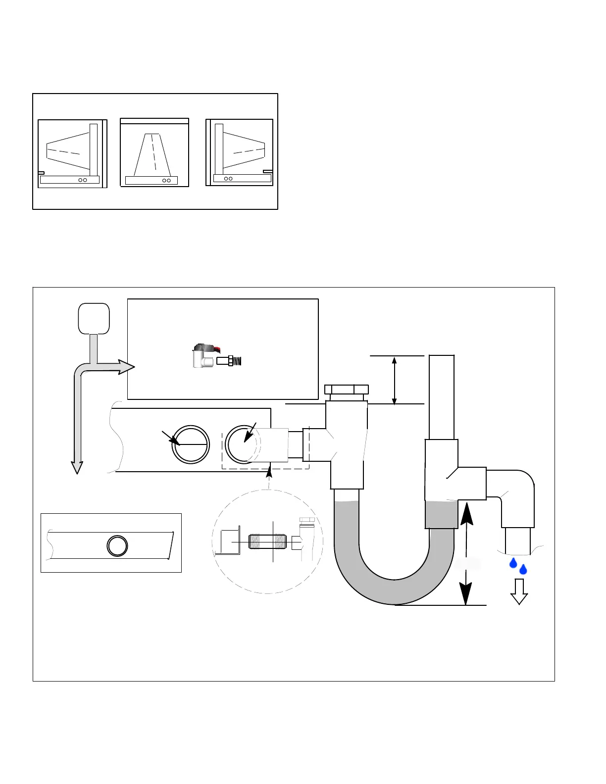
Figure 29. Main and Overflow Drain Locations based
on Main Drain
Connect the main drain and route downward to drain line or
sump. Do not connect drain to a closed waste system. See
Figure 30 for typical drain trap configuration.
Overflow Drain
It is recommended that the overflow drain is connected to a
overflow drain line for all units. If overflow drain is not
connected, it must be plugged with provided cap.
For downflow orientation, the overflow drain MUST be
connected and routed to a overflow drain line. See Figure
30 for main and overflow drain locations based on coil
orientation.
Best Practices
The following best practices are recommended to ensure
better condensate removal:
S Main and overflow drain lines should NOT be smaller
than both drain connections at drain pan.
S Overflow drain line should run to an area where
homeowner will notice drainage.
S It is recommended that the overflow drain line be
vented and a trap installed. Refer to local codes.
ABOVE
FINISHED
SPACE?
OVERFLOW DRAIN LINE
ALWAYS RUN AN OVERFLOW DRAIN LINE. IF NOT POSSIBLE TO
ROUTE OVERFLOW DRAIN LINE, INSTALL LOW VOLTAGE
OVERFLOW SWITCH KIT. WIRE KIT TO SHUT DOWN
COMPRESSOR PER INSTRUCTIONS.
NO
YES
LENNOX #
X3169
CLEAN OUT
VENT
PRESS IN
(DO NOT GLUE)
VENT MUST EXTEND
ABOVE HEIGHT OF
COIL DRAIN PAN BY
TWO INCHES (51MM)
1” X 3/4” X 3/4”
REDUCING
TEE WITH
PLUG
LENNOX
1
P-TRAP
49P66, J-TRAP #
91P90 OR ANY
PVC SCH 40 P- OR
J-TRAP 3/4”
OVERFLOW
DRAIN
AIR HANDLER DRAIN PAN
WHEN A COIL IS LOCATED ABOVE A FINISHED SPACE, A
3/4” (19.1MM) SECONDARY DRAIN LINE MUST BE:
S CONNECTED TO SECONDARY DRAIN PAN
OR
S CONNECTED TO THE OVERFLOW DRAIN OUTLET OF
THE AIR HANDLER DRAIN PAN.
TRAPS MUST BE DEEP ENOUGH TO OFFSET MAXIMUM STATIC DIFFERENCES —
GENERALLY, TWO INCHES (51MM).
DRAIN LINE SHOULD
SLOPE A MINIMUM OF
ONE INCH PER 10
FEET (25MM PER 3
METERS)
NOTE — WHEN A AIR HANDLER IS LOCATED
ABOVE A FINISHED SPACE THE SECONDARY
DRAIN PAN MUST HAVE A LARGER FOOTPRINT
THAN THE AIR HANDLER.
MAIN
DRAIN
TO APPROVED
DRAIN
FOR NEGATIVE PRESSURE COILS (BLOWER
AFTER COIL) TRAPS ARE REQUIRED ON ALL
DRAIN LINES CONNECTED TO COIL.
COMPACT OVERFLOW SWITCH WITH 3/4” FEMALE SLIP INLET
AND MALE ADAPTER, TWO PART DESIGN FOR USE WHERE
OBSTRUCTIONS PREVENT DIRECT THREADING
SECONDARY
DRAIN PAN
2”
(51MM)
TRAP DEPTH
1
LENNOX P-TRAP 49P66 REQUIRES A LARGER INSTALLATION SPACE THAN THE J-TRAP 91P90.
2
PIPE NIPPLE PROVIDED IN BAG ASSEMBLY - SCH 80, 3/4” I. D. X 5” - 34K7401 (1): CUT THE PIPE IN HALF AND USE IT TO ROUTE THE MAIN DRAIN.
MAIN
DRAIN
PROVIDED
PIPE NIPPLE
2
CUT TO
REQUIRED
LENGTH
SIDE VIEW
Figure 30. Main Drain

 Loading...


