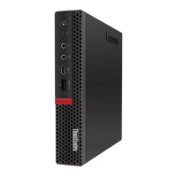
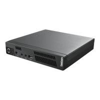
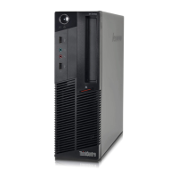
13 Padlock loop
Used to secure a padlock.
14 Smart cable clip slots
Used to secure a smart cable clip.
15 PCI-Express card area
To improve the operating performance of the computer, you can connect PCI-Express cards into this area.
Depending on the computer model, the connectors in this area vary.
16 Security-lock slot
Used to secure a Kensington-style cable lock.
System board
Note: See “Front view” on page 1 and “Rear view” on page 3 for additional component descriptions.
Figure 3. System board
1 4-pin power connector
2 Microprocessor fan connector
3 Memory slot (DIMM1) 4 Memory slot (DIMM2)
5 Memory slot (DIMM3) 6 Memory slot (DIMM4)
7 Power button board connector 8 Internal speaker connector
9 10-pin power connector
10 SATA power connector
Chapter 1. Overview 5
 Loading...