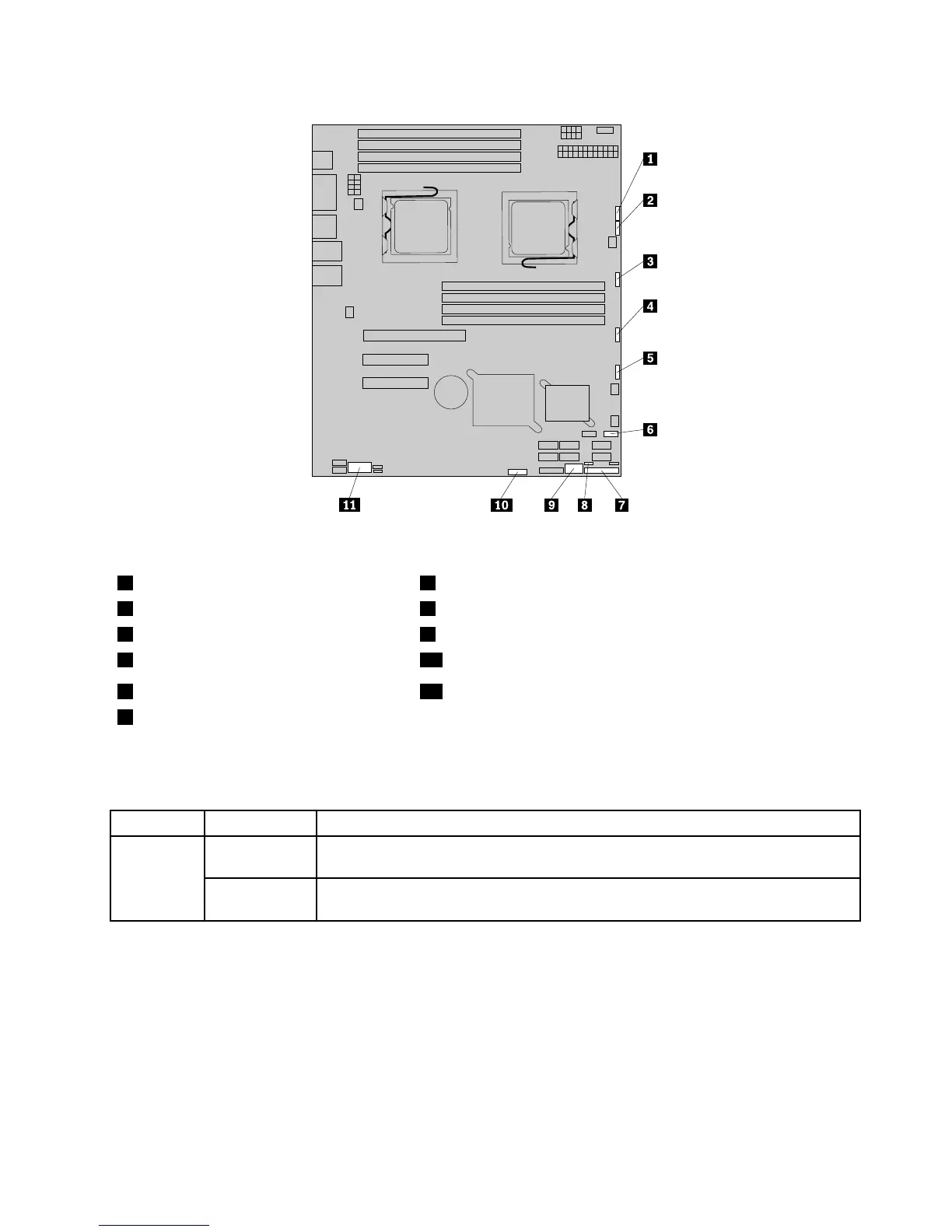
Figure6.Locatingotherconnectorsonthesystemboard
1J47(systemfan1connector)7J35(forfrontcontrolcable)
2J48(systemfan2connector)8JP1(ClearCMOSjumper)
3J50(systemfan3connector)9USB2connector
4J56(systemfan4connector)10J45connector(fortheSGPIOconnectorofthe4–portSATAcable)
5J49(systemfan5connector)11JP8(COM2connector)
6J19(frontUSBconnector)
Thefollowingtableintroducesthejumperswitchesonthesystemboard.
Table8.Jumpersettings
JumperPositionDescription
Pins1-2
Thedefaultpositionatwhichthejumperisplacedonpins1-2duringthenormal
operationofthesystem.
JP1:Clear
CMOS
Pins2-3
Ifthejumperisplacedonpins2-3,whenthejumperismovedbacktothedefault
position,thesettingsofCMOSwillbeclearedautomaticallyatthenextstartup.
Note:BeforeclearingtheCMOS,turnofftheserveranddisconnectthepowercord.Movethejumperfrom
pins1-2topins2-3.Waitmorethanveminutesandthenmovethejumperbacktothenormalposition
(pins1-2)toclearCMOS.
Chapter4.Locatingparts,controls,LEDs,andconnectors17