Diagnostics panel
The diagnostics panel provides controls, connectors, and LEDs.
Note: Diagnostics panel with an LCD display is available for some models. For details, see “LCD diagnostics
panel/handset” on page 29.
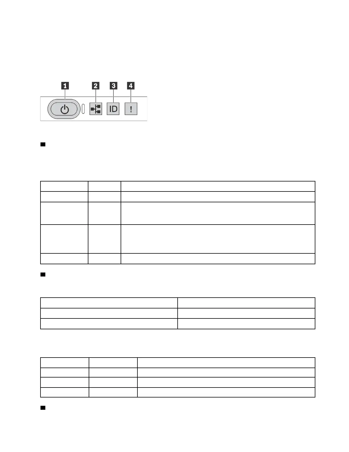
Figure 5. Diagnostics panel
1 Power button with power status LED
You can press the power button to power on the server when you finish setting up the server. You also can
hold the power button for several seconds to power off the server if you cannot shut down the server from
the operating system. The power status LED helps you to determine the current power status.
Status Color Description
Solid on Green
The server is on and running.
Slow blinking
(about one flash
per second)
Green The server is off and is ready to be powered on (standby state).
Fast blinking
(about four
flashes per
second)
Green The server is off, but the XClarity Controller is initializing, and the server is not
ready to be powered on.
Off
None There is no ac power applied to the server.
2 Network activity LED
Compatibility of the NIC adapter and the network activity LED
NIC adapater
Network activity LED
OCP 3.0 Ethernet adapter Support
PCIe NIC adapter Not support
When an OCP 3.0 Ethernet adapter is installed, the network activity LED on the front I/O assembly helps you
identify the network connectivity and activity. If no OCP 3.0 Ethernet adapter is installed, this LED is off.
Status Color
Description
On Green The server is connected to a network.
Blinking Green The network is connected and active.
Off None The server is disconnected from the network.
3 System ID button with system ID LED
Chapter 2. Server components 27

 Loading...


