Chapter 3. Internal cable routing
Some of the components in the server have internal cables and cable connectors. For details, see the
following cable routing sections:
•
“CFF RAIR/HBA adapter cabling routing” on page 54
• “FIO cable routing” on page 55
• “Intrusion switch cable routing” on page 56
• “Super capacitor cable routing” on page 57
• “7mm drive backplane cable routing (power & signal)” on page 59
• “M.2 drive backplane cable routing (power & signal)” on page 60
• “2.5-inch/3.5-inch drive backplane (power)” on page 61
• “2.5-inch/3.5-inch drive backplane (signal)” on page 62
Read the following guidelines carefully before you connect any cables:
• Power off the server before you connect or disconnect any internal cables.
• See the documentation that comes with any external devices for additional cabling instructions. It might
be easier for you to route cables before you connect the devices to the server.
• Cable identifiers of some cables are printed on the cables that come with the server and optional devices.
Use these identifiers to connect the cables to the correct connectors.
• Ensure that the relevant cables pass through the cable clips.
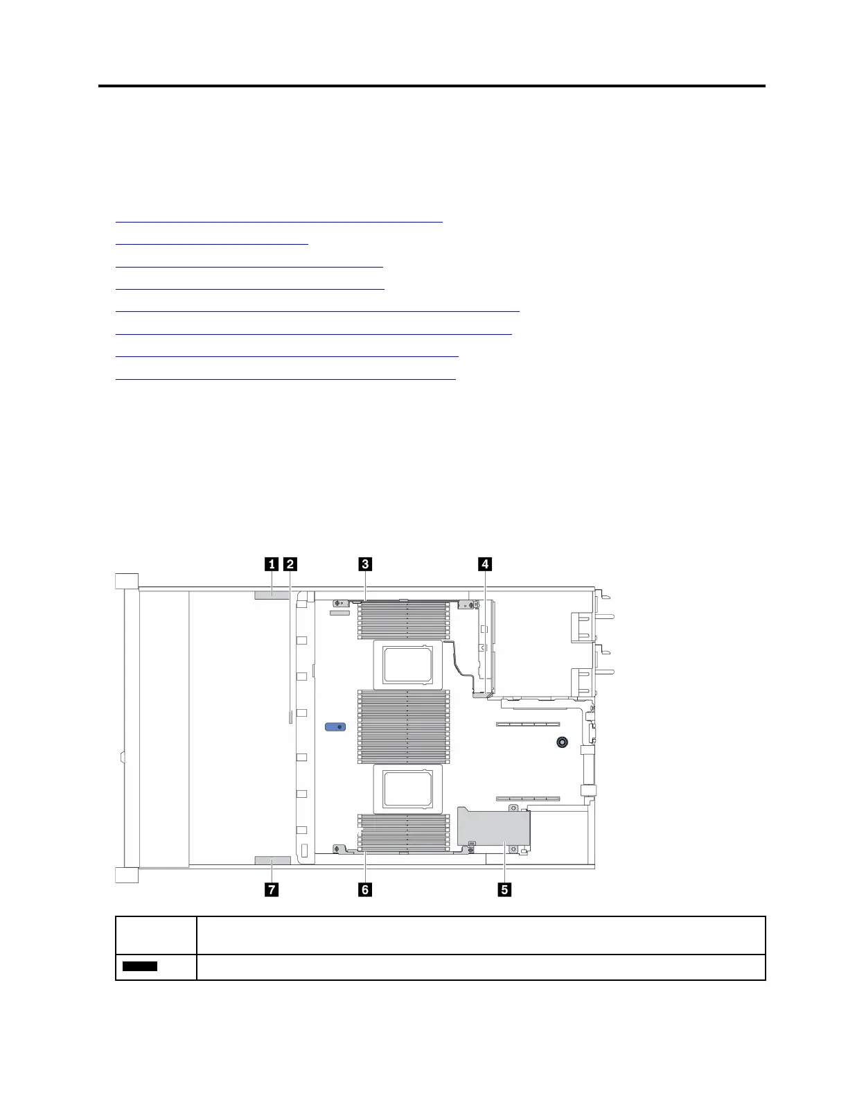
Cable
holder
Route
1 3 4
Route to BP Pwr connector, Raid Pwr connector, and PCIe connectors (4, 5, 7, 8)
© Copyright Lenovo 2020 51

 Loading...


