Front: one 4 x 3.5-inch AnyBay backplane
Rear: one 2 x 2.5-inch NVMe backplane
Con-
fig.
Front BP Rear BP
System board
Storage controller
SFF 8i RAID/HBA
5
NVMe 0–1
PCIe 3
NVMe 2–3 PCIe 7
SAS PCIe 2
NVMe 0, NVMe 1
PCIe 6
6
NVMe 0–1
PCIe 3
NVMe 2–3 PCIe 7
SAS
Gen 4: C 0
Gen 3: C 0, C 1
NVMe 0, NVMe 1
PCIe 6
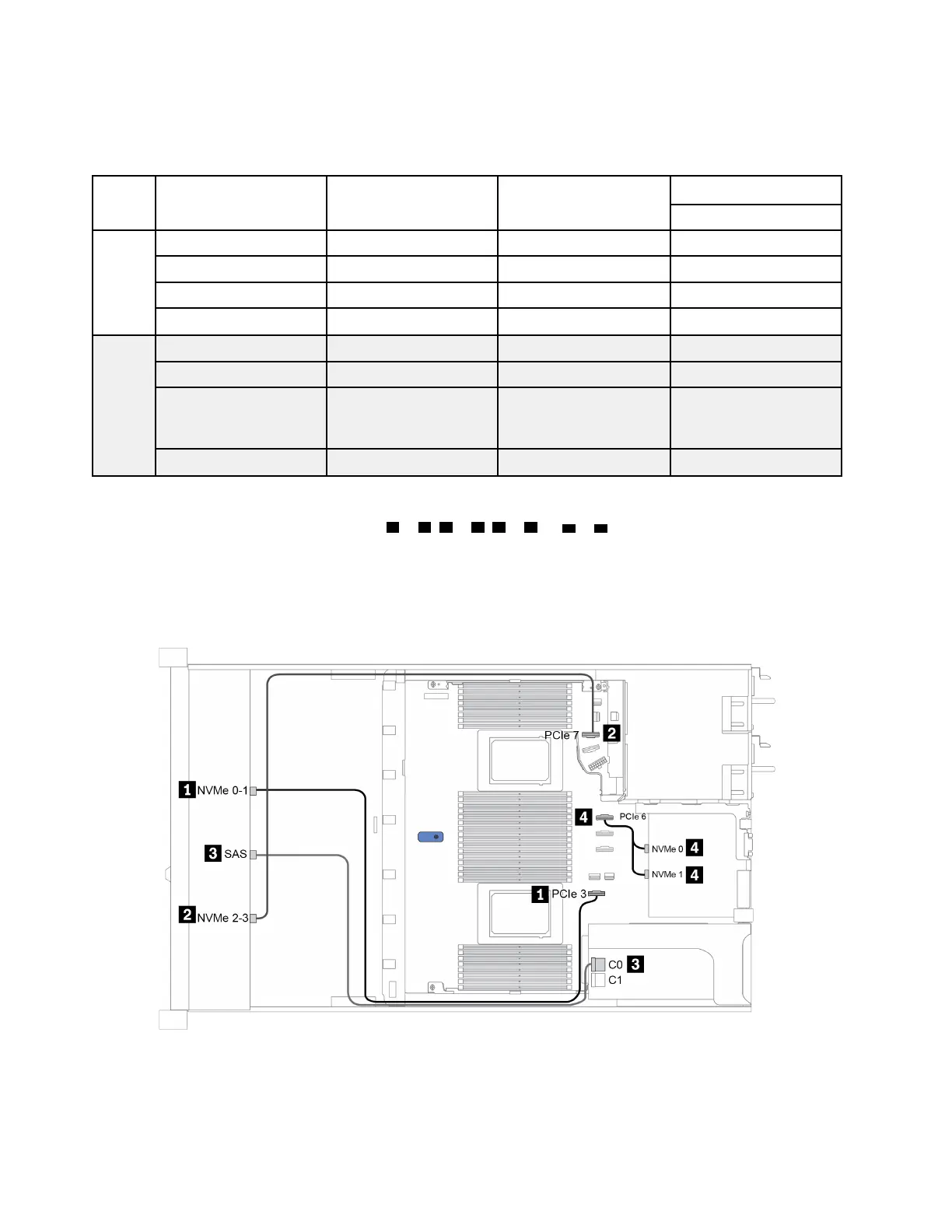
The following illustration shows the cable routing for the configuration 6, the routing for configuration 5 is
similar. Connections between connectors:
1 ↔ 1 , 2 ↔ 2 , 3 ↔ 3 , ... n ↔ n
Note: For models that support Gen 3 and Gen4 adapters at the same slot, the illustration shows only the
cable routing information for Gen 4 adapters, the routing and connector information is similar for Gen 3
adapters.
Figure 23. Cable routing for configuration 6
74 ThinkSystem SR645 Setup Guide

 Loading...


