Configurations 4 and 5: (front drive bays and rear drive bays)
Config.
Front BP Rear BP
System board
Storage controller
CFF 16i RAID/HBA
4
NVMe 0-1
PCIe 3
NVMe 2–3
PCIe 7
SAS 0 PCIe 2
SAS 1 PCIe 4
SAS 2 SAS PCIe 5
5
NVMe 0–1
PCIe 3
NVMe 2–3 PCIe 7
SAS 0 C 0
SAS 1 C 1
SAS 2 C 2
SAS C 3
PCIe 8 MB
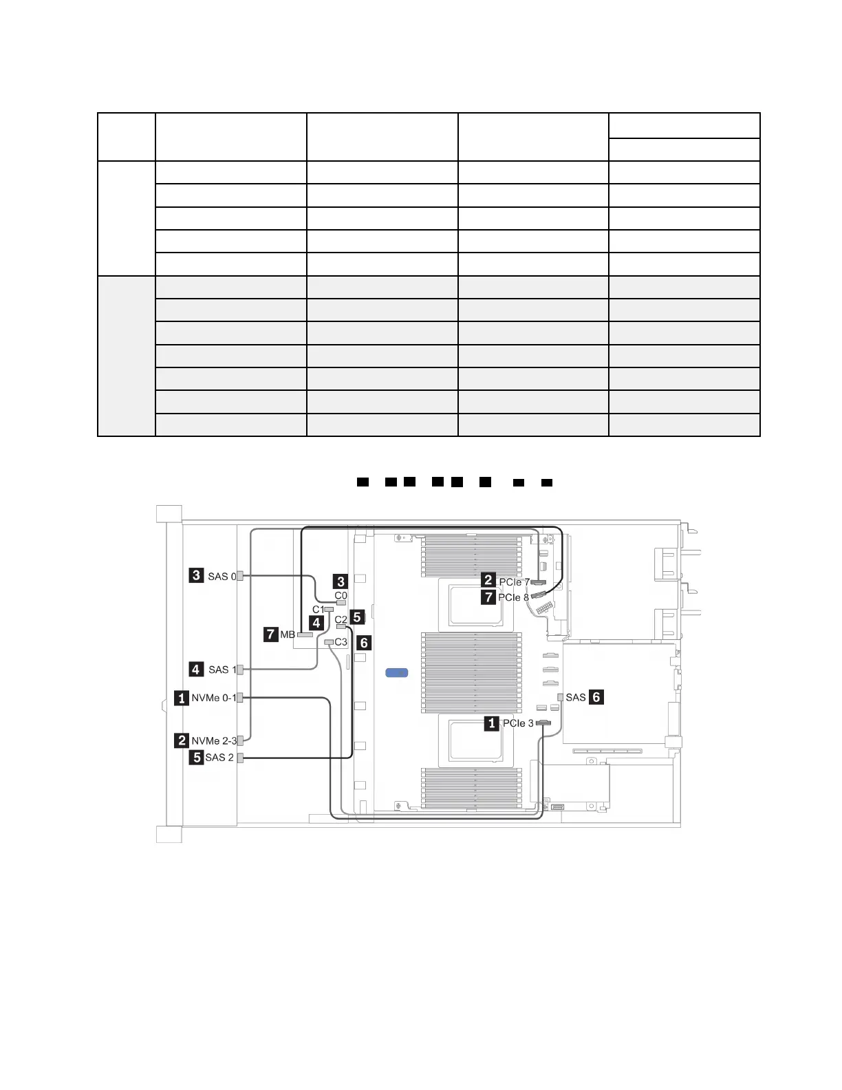
The following illustration shows the cable routing for the configuration 5, the routing for configurations 4 is
similar. Connections between connectors:
1 ↔ 1 , 2 ↔ 2 , 3 ↔ 3 , ... n ↔ n
Figure 28. Cable routing for configuration 5
Chapter 3. Internal cable routing 85

 Loading...


