Safety engineering
Device modules
SM301 safety module
1
24
EDS94AYAE EN 6.0
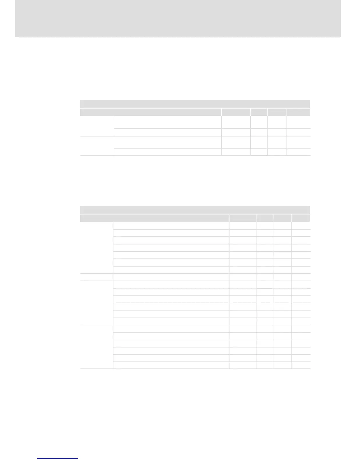
1.2.3.4 Technical data
24 V supply
The module and the safe output must be supplied with 24 V from safely separated power
supply units. To maintain electrical isolations, separate voltage supplies are required.
Detailed features of the 24−V supply
Terminal Specification [Unit] min. typ. max.
+, −
Supply voltage of the module via a safely separated
power supply unit (SELV/PELV)
[V] 19.2 24 30
Input current [mA] 350
24O, GO
Supply voltage of the safe output via a safely
separated power supply unit (SELV/PELV)
[V] 18 24 30
Input current [mA] 1100
If the voltage of the SELV/PELV power supply unit can exceed 30 V in the event of an error,
provide for an external fuse ( 1.1.8).
Inputs and output
The inputs and the output are isolated and designed for a low−voltage supply of 24 V DC.
The digital inputs are protected against polarity reversal.
Detailed features of the safe inputs and the safe output
Terminal Specification [Unit] min. typ. max.
I1A, I1B
I2A, I2B
I3A, I3B
I4A, I4B
AIE, AIS
PLC input, IEC−61131−2, 24 V, type 1
Low signal input voltage
V −3 0 5
Input current at low signal mA 15
High signal input voltage
V 15 24 30
Input current at high signal mA 2 15
Input capacitance
nF 3.5
Repetition rate of the test pulses
ms 50
AIE, AIS Input delay (operating time) s 0.3 10
CLA, CLB
PLC output, IEC−61131−2, 24 V DC, 50 mA
Low signal output voltage
V 0 0.8
High signal output voltage
V 17 24 30
Output current
mA 60
Cable capacity
nF 100
Cable resistance of a passive sensor
W 200
O1A, O1B
PLC output, IEC−61131−2, 24 V DC
Low signal output voltage
V 0 0.8
High signal output voltage
V 17 24 30
Output current
mA 500
Cable capacity
nF 100
Cable resistance
W 200
Tab. 1−1 Technical data
The chapter "Response times" must be observed as well ( 1.8).