Safety engineering
Device modules
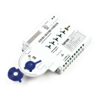
SM301 safety module
1
22
EDS94AYAE EN 6.0
Terminal assignment
Danger!
Danger to life through improper installation
Improper installation of the safety engineering systems can cause
anuncontrolled starting action of the drives.
Possible consequences:
ƒ Death or severe injuries
Protective measures:
Total cable length between X82 and its connected components (e.g. sensors,
devices, ...) > 3 m:
ƒ A shielded laying system must be used for the cable between X82 and its
connected components:
– The shield must at least cover the shield connection at the installation
backplane.
– The shield should also cover the connected component if possible.
ƒ Unshielded wiring is permissible from hardware version 1A.
Total cable length between X82 and its connected components (e.g. sensors,
devices, ...) < 3 m:
ƒ Unshielded wiring is permissible.
X82.1 Labelling Description
This part of the terminal strip is not assigned.
GO
GND SD−Out1
O1B
Safe monitor SD−Out1, channel B
O1A
Safe monitor SD−Out1, channel A
This part of the terminal strip is not assigned.
X82.2 Labelling Description
−
GND external supply
+
+24 V external supply via a safely separated power supply unit (SELV/PELV)
GIR
This part of the terminal strip is reserved.
RI1
GO
GND 24O
24O
+24 V external supply for the safe monitor SD−Out1 (SELV/PELV)
AIE
Error acknowledgement input ("Acknowledge In Error")
CLA Clock output for passive sensors, channel A (Clock A)
CLB Clock output for passive sensors, channel B (Clock B)
 Loading...
