M301L 21
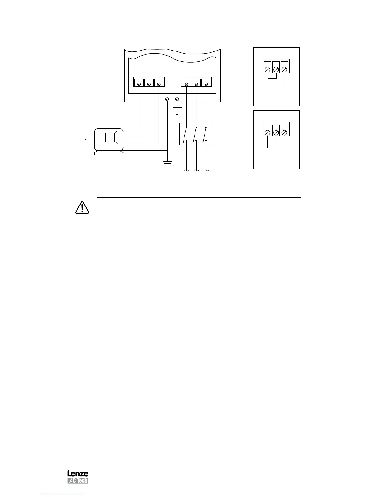
11 MC3000 POWER WIRING DIAGRAM
T1 T2
T3
L1 L2 L3
FUSED INPUT
VOLTAGE
GNDGND
GND
DISCONNECT
MEANS
(REQUIRED)
THREE PHASE
AC MOTOR
240 Vac SINGLE
PHASE INPUT
WIRING DIAGRAM
120 Vac SINGLE
PHASE INPUT
WIRING DIAGRAM
L1 L2 N
L1
L2
N
WARNING!
Do NOT connect incoming AC power to output terminals T1, T2 or
T3. Severe damage to the drive will result.
INSTALL, WIRE, AND GROUND IN ACCORDANCE WITH ALL APPLICABLE CODES.
NOTES:
1. Wire the motor for the proper voltage per the output rating of the drive. Motor wires
MUST be run in a separate steel conduit away from control wiring and incoming
AC power wiring.
2. Do not install contactors between the drive and the motor without consulting Lenze
AC Tech for more information. Failure to do so may result in drive damage.
3. Remove any existing, and do not install, power factor correction capacitors
between the drive and the motor. Failure to do so will result in drive damage.
4. Use only UL and CSA listed and approved wire.
5. Minimum wire voltage ratings: 300 V for 120, 200 and 240 Vac systems, and 600
V for 400, 480, and 590 Vac systems.
6. Wire gauge must be based on a minimum of 125% of the rated input/output
current of the drive, and a minimum 75 C insulation rating. Use copper wire only.
7. Wire and ground in accordance with NEC or CEC, and all applicable local codes.