M301L 67
19 MC3000 PID SETPOINT CONTROL
PID Setpoint Control allows the MC3000 to maintain a process setpoint, such as PSI or
CFM, without using an external controller. When PID is activated, the MC3000 will operate
in a closed-loop fashion, automatically adjusting the motor speed to maintain the setpoint.
PID setpoint control requires feedback from the process in order to compare the process
variable “value” to the setpoint. The difference between the process variable “value” and
the setpoint is called the error. The MC3000 will increase or decrease the motor speed
in an attempt to minimize the error. By constantly adjusting the motor speed, the PID
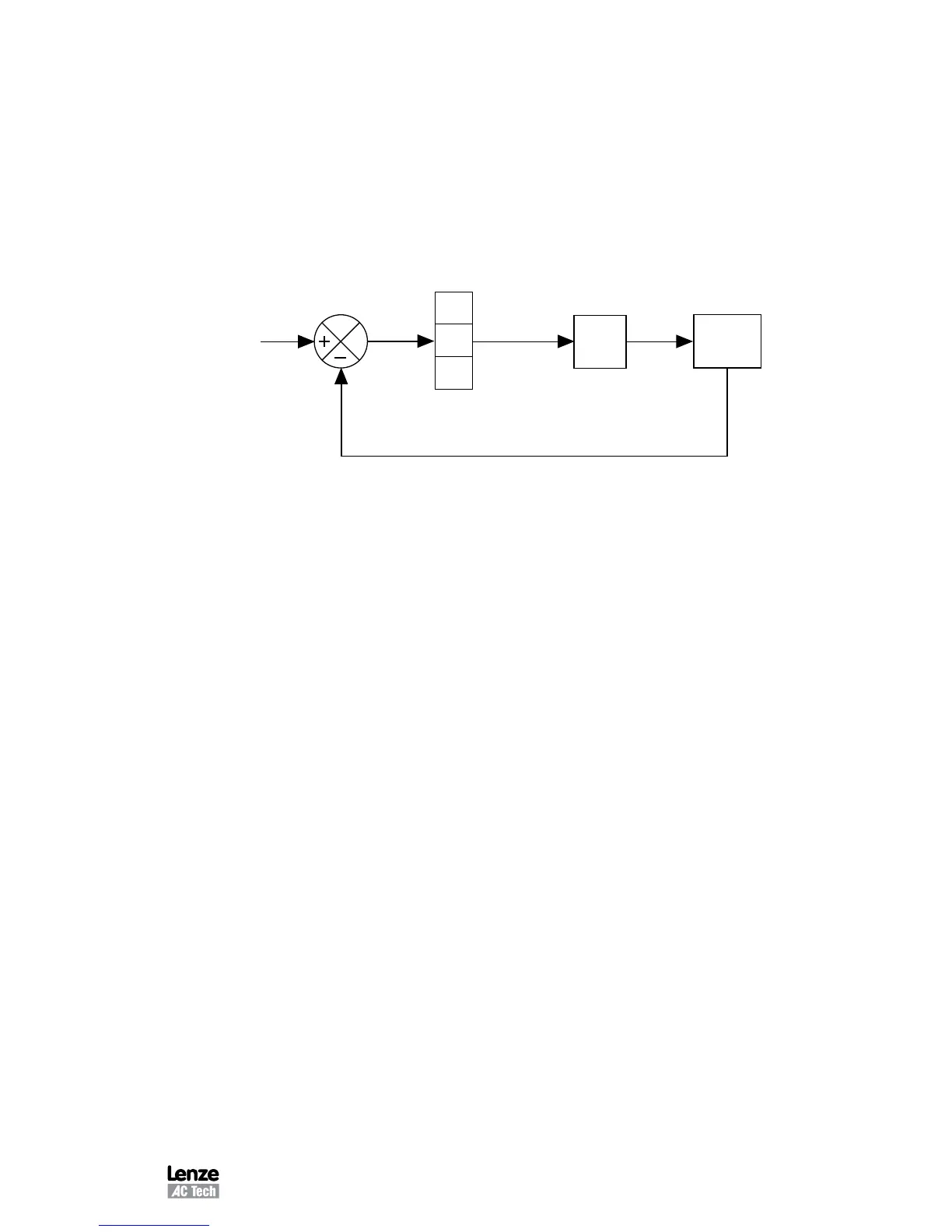
control will drive the process toward the setpoint. Refer to the PID block diagram below:
SETPOINT
Process Variable
Feedback (transducer)
Motor
Error
Speed
Command
P
I
D
Process
19.1 FEEDBACK DEVICES
A transducer or transmitter is required to monitor the process variable and provide
feedback to the PID unit in order to compare the process variable feedback to the setpoint.
A transducer outputs a signal corresponding to a fixed range of the process variable. A
transmitter provides offset and gain adjustments to allow the output signal to be adjusted
to correspond to different ranges of the process variable. Typical output signals for
transducers and transmitters are: 0-5 VDC, 0-10 VDC, or 4-20 mA. The feedback device
must be externally powered, as the drive does not have a power supply for such devices.
Program Parameter 74 - PID FB (PID FEEDBACK SOURCE) for the appropriate terminal
(TB-5A or TB-5B), and connect the feedback device as described below:
POT The positive signal wire (wiper) is connected to TB-5A, and the
“high” lead is connected to TB-6.
0-5, 0-10 VDC Connect the positive signal wire to TB-5A.
4-20 mA Connect the positive signal wire to TB-5B.
The common, or negative signal wire, is connected to TB-2 (circuit common).
Feedback devices can be direct or reverse acting. A direct acting device outputs a signal
that increases as the process variable increases. A reverse acting device outputs a signal
that decreases as the process variable increases. The programming of Parameters 75
- FB @ MIN and 76 - FB @ MAX depend on the type of feedback device being used.
When using a direct acting transducer, Parameter 75 - FB @ MIN should be set to the
value of the process variable feedback corresponding to the minimum feedback signal (0
VDC or 4 mA), and Parameter 76 - FB @ MAX should be set to the value of the process
variable feedback corresponding to the maximum feedback signal (5 or 10 VDC, or 20 mA).