M301L 35
15.3 THREE-WIRE START/STOP CONTROL
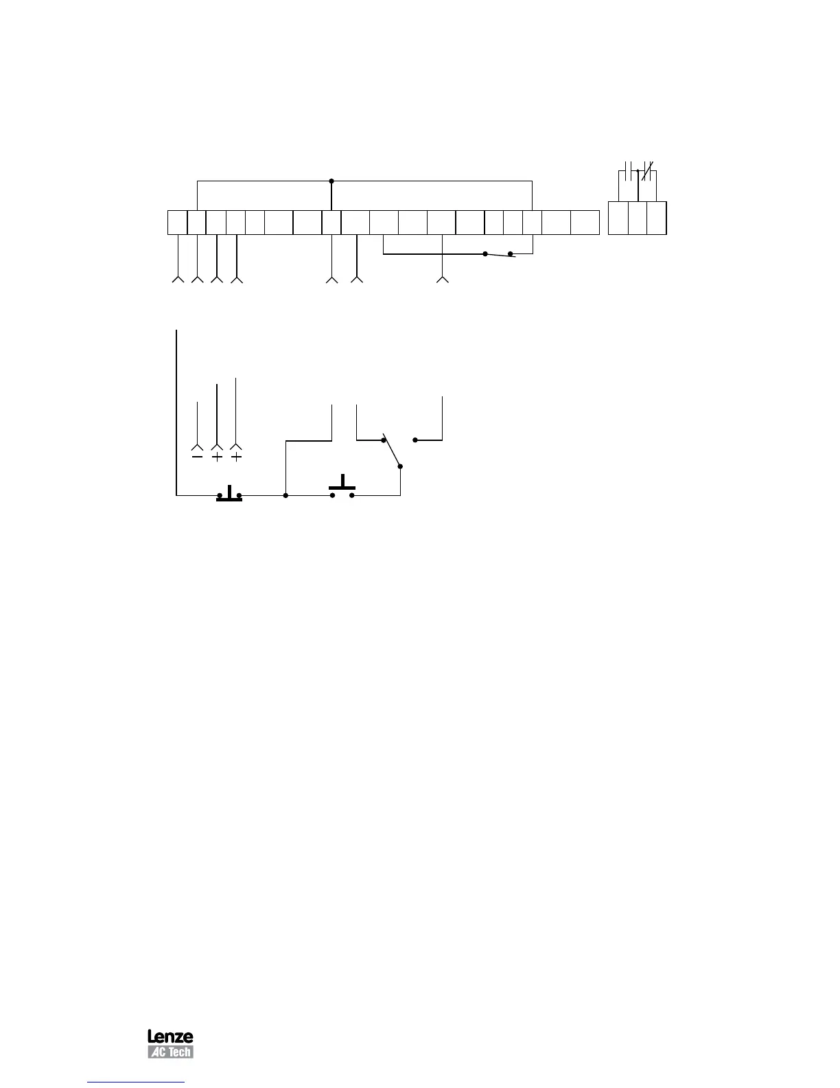
Shown below is the wiring diagram for a typical three-wire start/stop control scheme,
using momentary contacts (such as pushbuttons) for START and STOP commands.
Also shown is the wiring for a 0-10 VDC or 4-20 mA speed reference signal
STOP
CIRCUIT COMMON
0-10 VDC INPUT
4-20 mA INPUT
CIRCUIT COMMON
START FORWARD
MOMENTARY
STOP CONTACT
1 2 5A 5B 6 10A 12A RXA TXB10B 2 13A 13B 13C 13D 14 15 2
16 17 18
START REVERSE
0-10 VDC or 4-20 mA
SELECT (see Note 3)
FWD REV
(see Note 2)
MOMENTARY
START CONTACT
The TB-2 terminals are internally tied together
NOTES:
1. Momentarily close TB-12A to TB-2 to START, and momentarily open TB-1 to
TB-2 to STOP.
2. If REVERSE direction is required, TB-13C must be set to START REVERSE
(refer to Parameter 49 - TB13C). If REVERSE is not required, connect the other
side of the start button to TB-12A.
3. Program TB-13A, 13B, or 13C to select the appropriate speed reference signal
that will control the drive speed (refer to Parameters 47, 48, and 49). When that
TB-13 terminal is closed to TB-2, the drive will respond to the selected speed
reference signal. In the diagram above, TB-13A is programmed to select either
a 0-10 VDC or 4-20 mA signal.
4. If the contact closure is not made between TB-13A and TB-2 to select a speed
reference, the drive will default to keypad speed control.