Braking operation
Braking operation with brake resistor
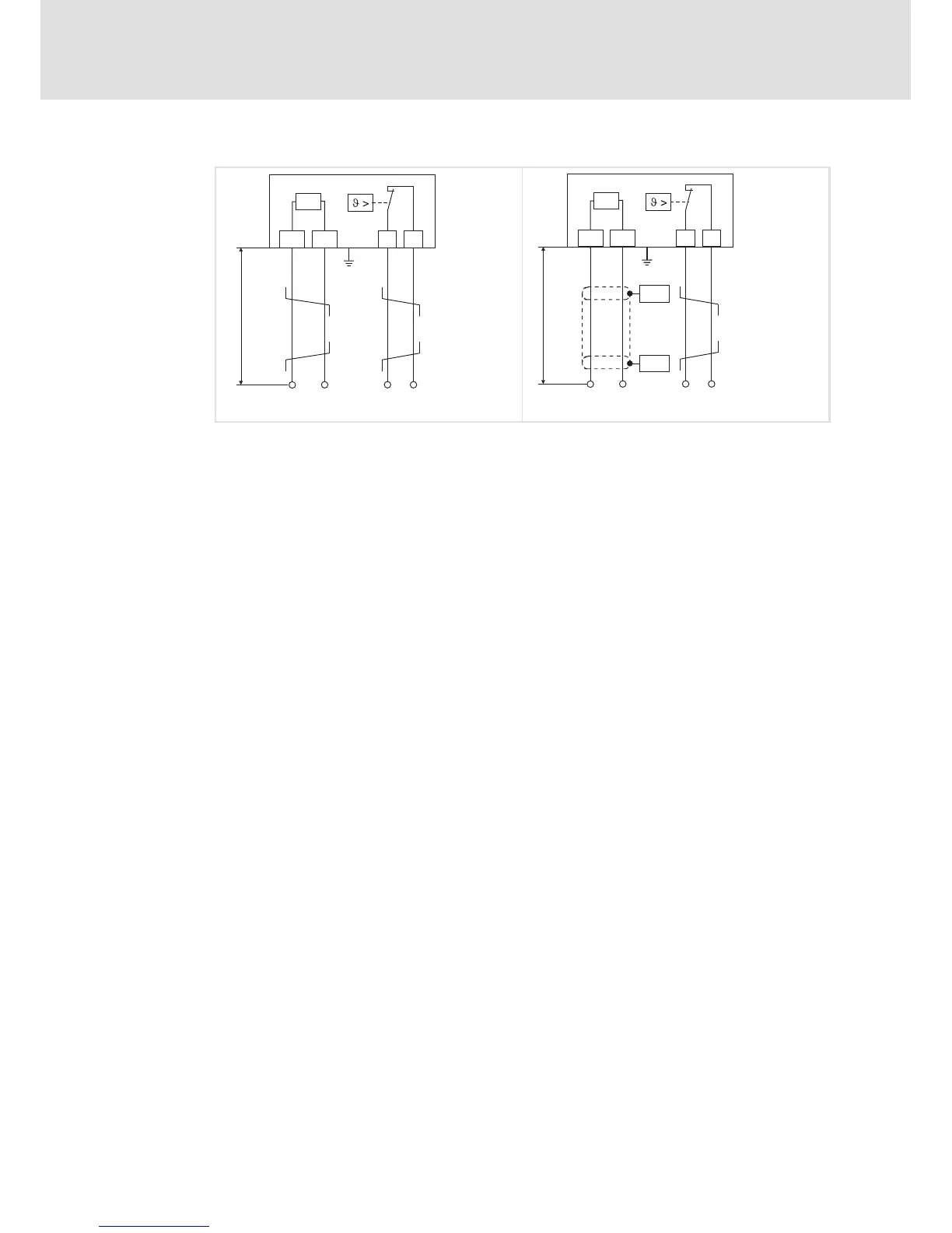
Wiring of brake resistor
7
99
EDS84DG752 EN 5.0
Wiring principle
R
B
RB1 RB2
< 0.5 m
PE
T1 T2
R
B
RB1 RB2
<5m
PE
PES
PES
T1 T2
ERBG008 ERBG007
Fig. 7-1 Wiring of a brake resistor to the controller
PES HF-shield termination by PE connection via shield clamp
Rb1, Rb2 Terminals of the brake resistor
Supply cable to the controller
T1, T2 Terminals temperature monitoring of the brake resistor (thermal contact/NC
contact)
Supply cable for evaluation of temperature monitoring
(to be integrated e.g. into the latch circuit of the mains contactor of the supply)
The brake resistor is thermally stressed due to converted braking power and may be
thermally destroyed as a consequence of excessive braking power.
To avoid thermal overload of the brake resistor:
ƒ set additional parameters in the »Engineer«
or
ƒ implement external wiring using a temperature contact on the brake resistor (e.g.
interrupted supply and activation of the mechanical brakes).
To protect the brake resistor:
ƒ use the monitoring of the I
2
xt utilisation of the controller which is proportional to
the converted braking power.