Features
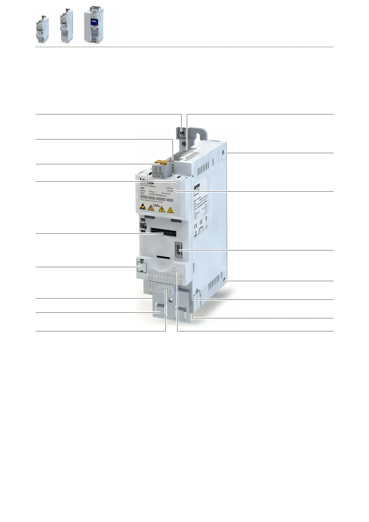
The following gures give an overview of the elements and connecons on the devices. Posi-
on, size and appearance of elements and connecons may vary depending on the capacity
and size of the equipment.
Some equipment may be oponal.
Example of 0.25 kW ... 2.2 kW
X105 brake resistor connec!on
DC-bus X100 connec!on
from 0.55 kW
Slot
Diagnos!c module
Standard I/O or Applica!on I/O
Control connec!ons
PTC input X109
DIP switch or rotary encoder switch
Op!on
Op!on
Motor connec!on X105
Network status LEDs
IT screw
Network shield connec!on
Inverter status LEDs
Basic network se" ngs
IT screw
Safety module X1
Shield connec!on
Control terminals X3
Memory module X20
Interface X16
Network X2xx
Relay output X9
Mains connec!on X100PE connec!on
Product informaon
Features
15

 Loading...


