Further control connecons
Terminal descripon Relay output
Connecon X9
Connecon type pluggable screw terminal
Max. cable cross-secon mm² 1.5
Max. cable cross-secon AWG 14
Stripping length mm 6
Stripping length inch 0.24
Tightening torque Nm 0.2
Tightening torque lb-in 1.8
Required tool 0.4 x 2.5
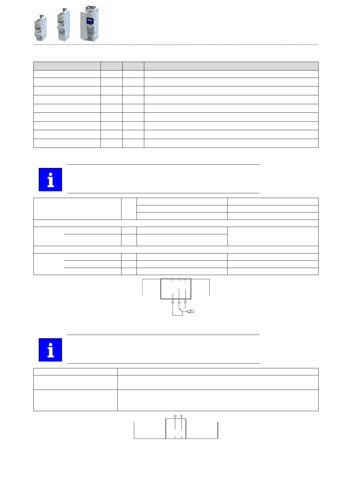
Relay output
Relay is not suitable for direct switching of a electromechanical holding brake!
Use a corresponding suppressor circuit in case of an inducve or capacive
load!
Connecon Terminal X9: COM Centre contact (common)
Terminal X9: NC Normally-closed contact
Terminal X9: NO Normally-open contact
Minimum DC contact load
Voltage V 10 A correct switching of the relay contacts
needs both values to be exceeded simultane-
ously.
Current mA 10
Switching voltage/switching current
Maximum
AC 240 V A 3 According to UL: General Purpose
DC 24 V A 2 According to UL: Resisve
DC 240 V A 0.16
PTC input
In the Lenze seng, motor temperature monitoring is acvated! In the delivery
status, there is a wire jumper between the terminals T1 and T2. Before connect-
ing a thermal sensor, remove the wire jumper.
Use Connecon of PTC or thermal contact
Connecon Terminal X109: T1
Terminal X109: T2
Sensor types PTC single sensor (DIN 44081)
PTC triple sensor (DIN 44082)
Thermal contact
Product extensions
Further control connecons
PTC input
217

 Loading...


