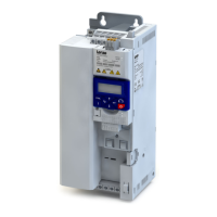
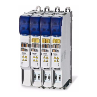
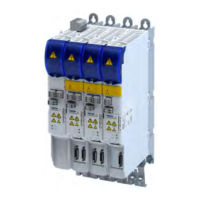
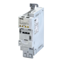
Preparaon
Further data and in
formaon for mechanical mounng:
4Control cabinet structure ^ 32
4Dimensions ^ 86
The scope of supply of the inverter comprises mounng ins
trucons. They
describe technical data and informaon on mechanical and electrical
installaon.
Mounng posion
•
Vercal alignment - all mains connecons are at the top and the motor connecons at the
boom.
Free spaces
•
Maintain the specied free spaces above and below to the other installaons.
Mechanical installaon
•
The mounng locaon and material must ensure a durable mechanical connecon.
•
Do not mount onto DIN rails!
•
In case of connuous vibraons or shocks use vibraon dampers.
How to mount the inverters onto the mounng plate.
Precondions:
•
Mounng plate with conducve surface
Required:
•
Tool for drilling and thread cung
•
Screwdriver
•
Screw and washer assemblies or hexagon socket screws with washers.
1.Prepare mounng plate with corresponding threaded holes.
2.Fit screws and washers (if applicable).
3.Do not yet ghten the screws.
4.Mount the inverter on the prepared mounng plate via keyhole suspension.
5.Only ghten the screws hand-ght.
6.Pre-assemble further units if necessary.
7.Align the units with each other.
8.Screw the units onto the mounng plate.
The inverters are mounted on the mounng plate. You can begin with the wiring.
Screw and washer assemblies or hexagon socket screws with washers are recommended..
M5 x ≥ 10 mm for devices up to and including 2.2 kW
M5 x ≥ 12 mm for devices up to and including 11 kW
M6 x ≥ 16 mm for devices up to and including 22 kW
M8 x ≥ 16 mm for devices up to and including 110 kW
Informaon on mechanic
al installaon
Preparaon
37



 To Next Page