Installation
Electrical installation
Terminal assignment
5
28
EDS82ZAFPC010 EN 4.0
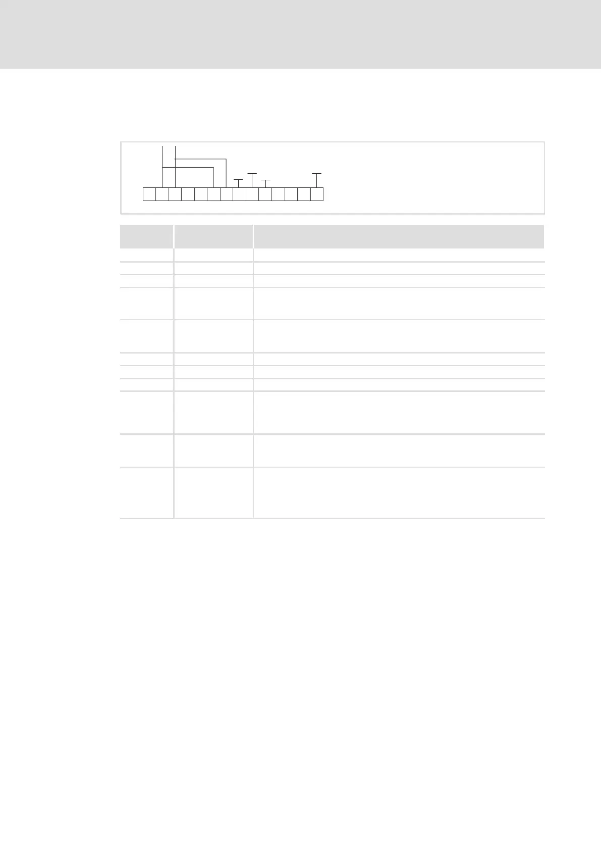
5.2.4 Terminal assignment
E82ZAFPC001function module
GND1
GND1
B
CN
7
20 59
+5V
+20V
AVP
2839
7
BA
GND2
40
GND3
+
X3
E82ZAFP001
Terminal
X3/
Designation Function / level
PES Additional HF−shield termination
A T/R(A) RS485 data line A
B T/R(B) RS485 data line B
CN CNTR For function see PROFIBUS standard *)
l Level during data transmission: CNTR = HIGH
(+5 V DC, reference:GND3)
VP For function see PROFIBUS standard *)
l U = +5 V DC (reference:GND3)
l I
max
= 10 mA
40 GND3 Reference potential for PROFIBUS network *)
7 GND1 Reference potential for X3/20
39 GND2 Reference potential for controller inhibit (CINH) at X3/28
28 CINH Controller inhibit
l Start = HIGH (+12 ... +30 V DC)
l Stop = LOW (0 ... +3 V DC)
(reference: GND2)
20 DC voltage source for internal supply of controller inhibit (CINH)
l +20 V DC (reference: GND1)
l I
max
= 20 mA
59 External DC voltage supply for the function module
l +24VDC±10% (reference: GND1)
l Current consumption on 24 V DC: 80 mA
The current for looping through the supply voltage to other nodes via
terminal 59 must be max. 3A.
*) E.g. for repeater connection