Installation and commissioning
DIGIDRIVE
Variable speed drive
22
Réf. 3218 GB - 4.33 / d - 02.02
LEROY-SOMER
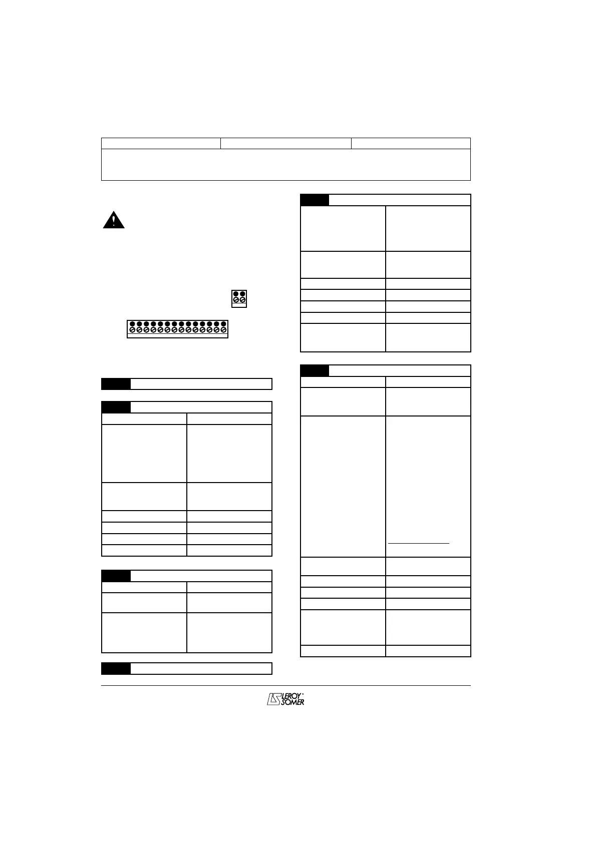
3.3.2 - Control terminal blocks
• The DIGIDRIVE is factory set
with a positive logic configuration.
• All the terminal block
explanations are given for positive logic.
• Using a drive with a control
system which has a different control
logic may cause unwanted starting of
the motor.
The maximum tightening torque for the
control terminals is 0.6 N.m.
1 0V common
2 Analogue voltage input (A1)
Voltage range 0 to +10V
Scale 0V corresponds to
minimum speed
(0
0
1
1
)
10V corresponds to
the maximum speed
value (0
0
2
2
)
Absolute maximum
voltage range
-18 to +35V in
relation to the 0V
common
Input impedance 100 kΩ
Resolution 0.1% (10 bits)
Accuracy ± 2%
Sampling time 6 ms
3 +10V potentiometer power supply
Voltage accuracy ± 2%
Maximum output
current
5mA
Protection Designed to
tolerate a
permanent short-
circuit at the 0V
4 0V common
PL1
PL2
15
1234567891011121314
16
5 Analogue current input (A2)
Current range 0-20mA, 20-0mA,
4-20mA and 20-
4mA with or without
detection of
signal break.
Absolute maximum
voltage range
-18V to +30V in
relation to the 0V
common
Input impedance 200 Ω
Resolution 0.1% (10 bits)
Accuracy ± 2%
Sampling time 6 ms
Factory setting 4-20mA without
detection of
signal break
6 Analogue output
Voltage range 0 to +10V
Absolute maximum
voltage range
-1V to +35V in
relation to the 0V
common
Scale Motor frequency
image output:
• 10V corresponds
to the maximum
frequency 0
0
2
2
or
Motor load image
output:
• 10V corresponds
to
150% of the
current at full load:
Output voltage =
Maximum current
output
5mA
Resolution 0.1% (10 bits)
Accuracy ± 5%
Update time 22 ms
Protection Designed to
tolerate a
permanent short-
circuit at the 0V
Factory setting Motor frequency
I active
1.5 x I nom var.
x 10
 Loading...