Electrical connection
Leuze electronic MLC 520 35
Pin Core color (CB-M12-xx000E-5GF) Transmitter
FE FE - functional earth, shield
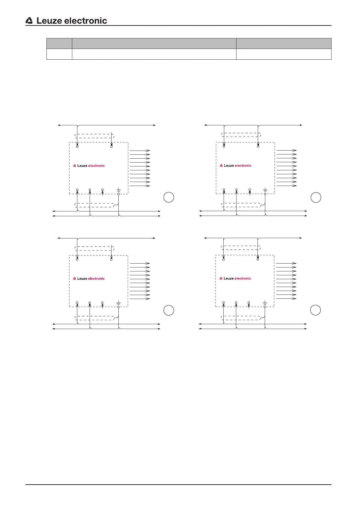
The polarity of the supply voltage selects the transmission channel of the transmitter:
• VIN1=+24V, VIN2=0V: transmission channelC1
• VIN1=0V, VIN2=+24V: transmission channelC2
The wiring of pin4 determines the transmitting power and thereby the range:
• Pin4=+24V: standard range
• Pin4=0V or open: reduced range
VIN1
1
RNG
4
VIN2
3
FE
5
-A1
MLCx00T
n.c.
2
+ 24V
FE
0V
+ 24V
FE
0V
1
WH
GY
BU
BN
BK
VIN1
1
RNG
4
VIN2
3
FE
5
-A1
MLCx00T
+ 24V
FE
0V
+ 24V
FE
0V
2
n.c.
2
WH
GY
BU
BN
BK
VIN2
3
RNG
4
VIN1
1
FE
5
-A1
MLCx00T
+ 24V
FE
0V
+ 24V
FE
0V
3
n.c.
2
WH
GY
BN
BU
BK
VIN2
3
RNG
4
VIN1
1
FE
5
-A1
MLCx00T
+ 24V
FE
0V
+ 24V
FE
0V
4
n.c.
2
WH
GY
BN
BU
BK
1 Transmission channel C1, reduced range
2 Transmission channel C1, standard range
3 Transmission channel C2, reduced range
4 Transmission channel C2, standard range
Fig.7.2: Connection examples transmitter




 To Next Page