Display elements
Leuze electronic SOLID-4 23
TNT 35/7-24V
DEUTSCHENGLISHFRANÇAISITALIANOESPAÑOLNEDERLANDS
5.2 SD4R-E Receiver status displays
Two LEDs and one 7-segment display report the receiver's operating status.
5.2.1 7-segment displays
After the electrical supply voltage is turned on, the following data appear on the receiver’s
7- segment display:
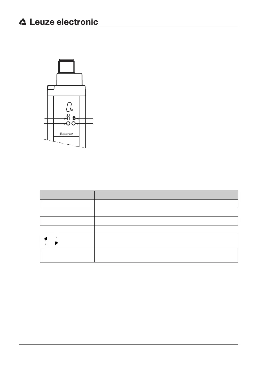
a = Symbol for OSSDs
b = LED1 (green/red)
c = Symbol for RES
d = LED2, yellow
Fig. 5.2-1: SD4R-E Receiver status displays
7-segment display Meaning
8. Hardware reset when turned on
S Self test running (for approx. 1.5 s)
1 Normal operation, channel 1
2 Normal operation, channel 2
F = Device fault
x = Fault number, alternating with "F"
1 or 2 flashing Flashing transmission channel number → W
eak signal,
device not
optimally aligned or dirty
Table 5.2-1: SD4R-E R
eceiver 7-segment display

 Loading...


