User Manual for BPS-200
www.levitronix.com
PL-4012-00, Rev07, DCO# 20-144
4.1.3 Electrical Installation of Controller LPC-200.1 for Standalone Operation
For standalone operation the LPC-200.1 is disabled when power is turned on. It can be enabled manually by
using the “UP” button on the display. However, if the controller shall be enabled automatically, when power is
applied the “ENABLE” pin on the “USER INTERFACE” connector (see Table 10) has to be active (typically
24V).
4.1.4 Electrical Installation of Controller LPC-200.1 for Extended Operation
If the LPC-200.1 shall to be controlled with external signals the “USER INTERFACE” can be used with the
PIN designations described in Table 10.
4..20 mA = 0..10000 rpm
-> Cut-off (min.) speed = 300 rpm
Direct connection, no protection.
Galvanic isolation on the user
side is required.
24 V active
0 V not active
Is needed to enable the system
with an external signal.
Relay closed active, system on
Relay open not active, system off
This signal indicates if the
system is active.
Table 10: Description of „USER INTERFACE“ connector
(Description is for standard firmware, for other configurations refer to alternate firmware documentation)
Figure 23: „ENABLE“ connector
- Delivered with controllers
- Supplier: PTR Messtechnik GmbH, Germany
- Connector Type: AK1550/06-3.81-GREEN
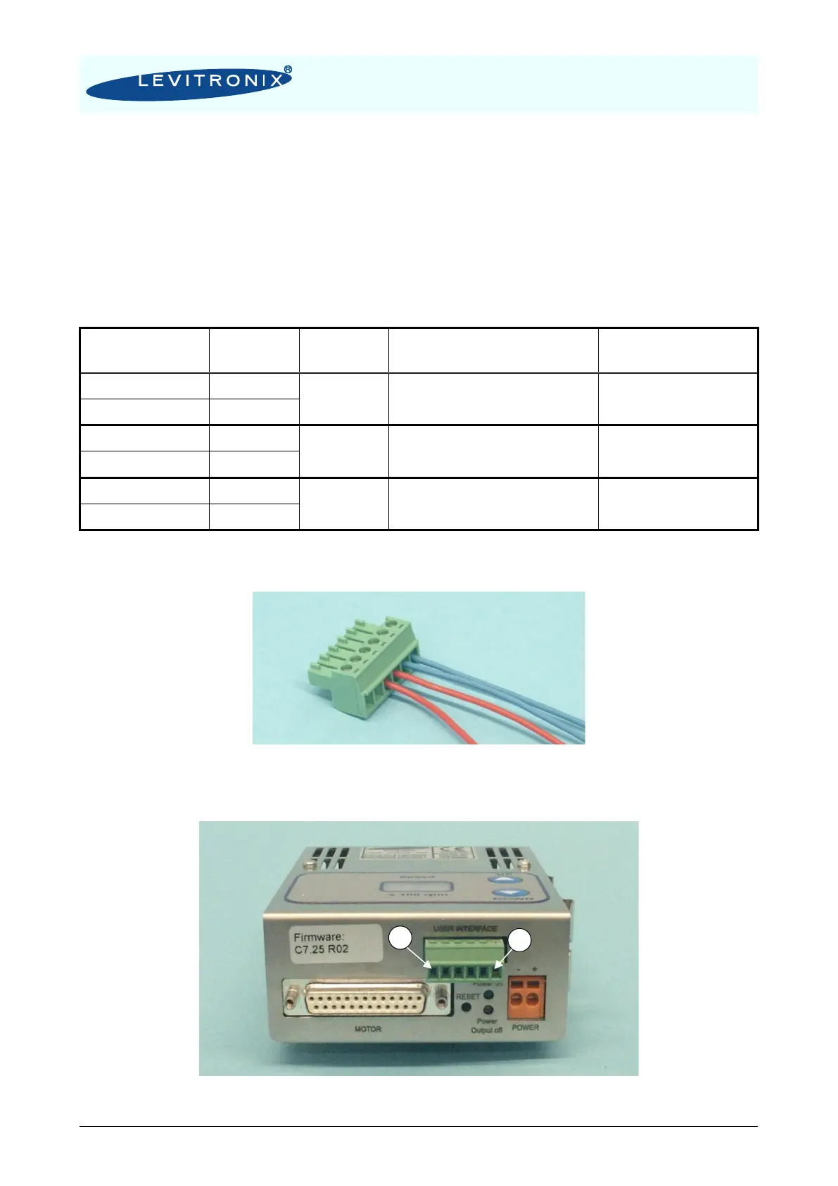
Figure 24: Mounted “USER INTERFACE” connector and Pin numbering