orliquid/mot gradient eTemperaturtgetemperatur AmbientT
etemperatur LiquidTetemperatur MotorT
CTtgCTCTCTTTTT
LMA
LM
ALMLALMALM
17 Figure see
14 Figure see
==
==
−+−+== )25()25()25,25(),(
0000
All above presented thermal data are typical values, which are partly based on measurements and partly on
interpolations with a simplified thermal model and are therefore only guideline values and are suitable for a
first layout of the basic thermal concept. It is recommended to check the thermal values with the motor
placed on the final location and under worst case performance conditions of the application.
In order to account for thermal variations (like ambient temperature, closed chemical cabinets or corners
without ventilations) and to not significantly reduce the MTBF of the motor it is recommended to keep about
20
0
C safety distance to the absolute thermal limit of the motor (90
0
C) when designing the thermal concept
of the pump system.
3.4.2 Controller Temperature
Depending on the ambient temperature and the placement of the controller additional cooling may be
required (see Figure 18). To improve cooling of the controller, place the device into a moving air stream. If
the controller is mounted in a compact area or adjacent to additional heat sources (e.g. a 2
nd
controller)
ensure that there is sufficient ventilation.
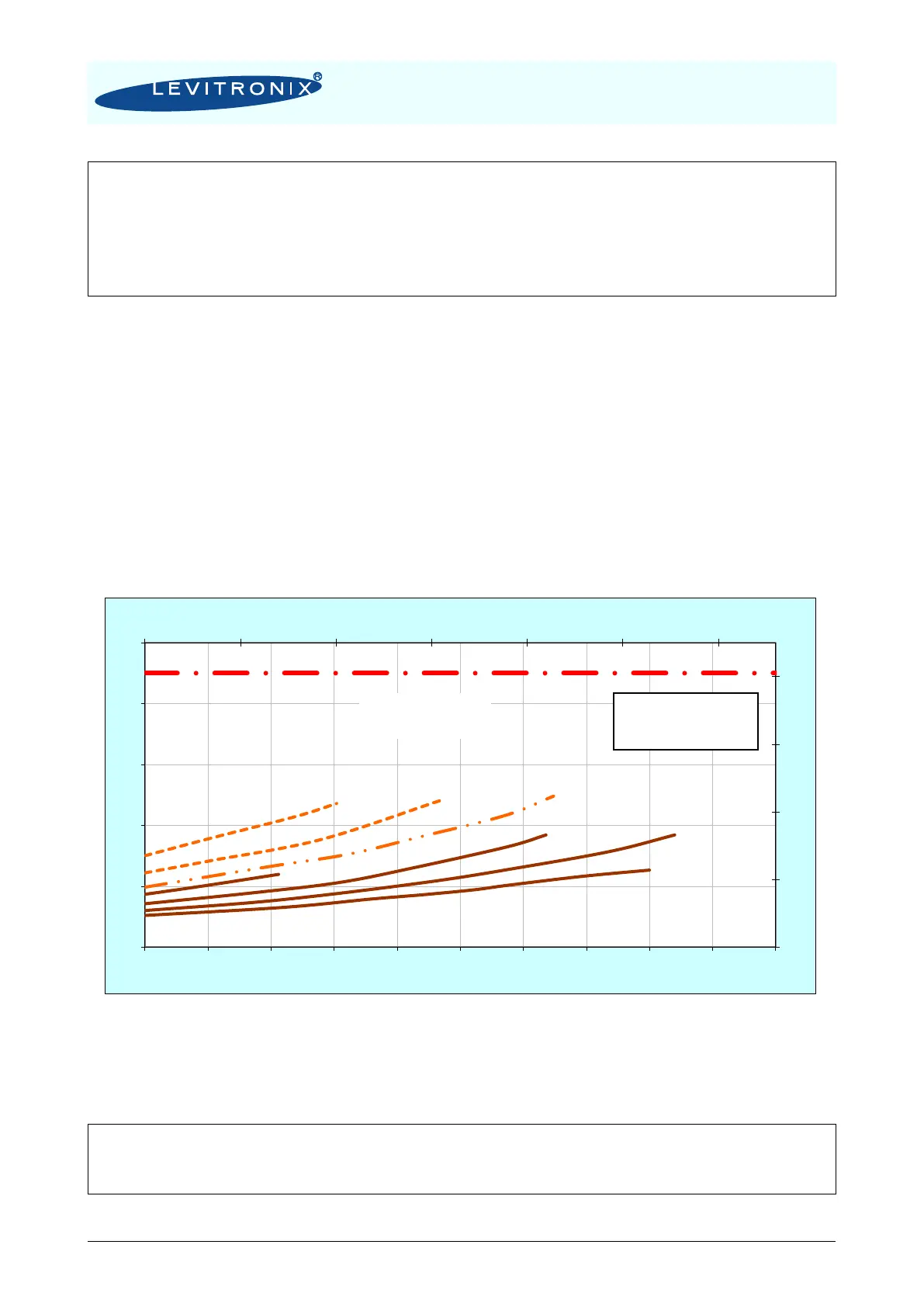
Figure 18: Temperature curves of controller LPC-200 vs. flow and speed
(For pumping with pump head LPP-200.1 and motor BSM-1.x. Representative for LPP-200.11)
The above curves are measurements of the controller temperature at 25
0
C ambient. Equation (Eq. 2) shows
how to calculate the controller temperature for at other ambient temperatures based on this curve.