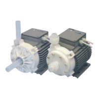
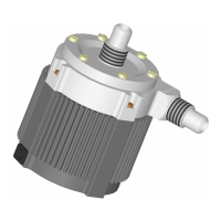
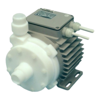
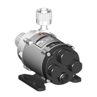
User Manual for BPS-2000
www.levitronix.com
PL-4021-00, Rev03, DCO# 15-235
Table of Content
1 SAFETY PRECAUTIONS ............................................................................................................................................................... 3
2 SPECIFICATIONS.......................................................................................................................................................................... 4
2.1 Specification of Components ................................................................................................................................................. 4
2.2 Standard System Configurations ........................................................................................................................................... 6
2.2.1 Standalone System Configuration ..................................................................................................................................................................... 6
2.2.2 Extended System Configuration ........................................................................................................................................................................ 6
2.2.3 ATEX / IECEx System Configuration ................................................................................................................................................................. 7
2.3 General Environmental Conditions ........................................................................................................................................ 7
2.4 Pressure-Flow Curves ........................................................................................................................................................... 8
2.5 NPSHr Curves ...................................................................................................................................................................... 9
2.6 Maximum Static Pressure for Pump Heads ......................................................................................................................... 10
2.7 Basic Dimensions of Main Components .............................................................................................................................. 11
3 ENGINEERING INFORMATION ................................................................................................................................................... 14
3.1 Sealing and Material Concept ............................................................................................................................................. 14
3.2 AC Supply and Power Consumption ................................................................................................................................... 16
3.2.1 Power Consumption ......................................................................................................................................................................................... 16
3.2.2 AC Input Voltage and Grid Currents ................................................................................................................................................................ 17
3.2.3 Inrush Current .................................................................................................................................................................................................. 17
3.2.4 Earth Leakage Current..................................................................................................................................................................................... 17
3.2.5 Recommendations for Circuit Breaker Design ................................................................................................................................................ 17
3.3 Temperature Monitoring ...................................................................................................................................................... 18
3.4 Thermal Management ......................................................................................................................................................... 19
3.4.1 Motor Temperature .......................................................................................................................................................................................... 19
3.4.2 Controller Temperature .................................................................................................................................................................................... 22
3.5 Hydraulic Circuit Design ...................................................................................................................................................... 23
4 INSTALLATION ........................................................................................................................................................................... 24
4.1 Electrical Installation of Controller ....................................................................................................................................... 24
4.1.1 Overview .......................................................................................................................................................................................................... 24
4.1.2 General Installation Instructions ...................................................................................................................................................................... 26
4.1.3 Electrical Installation of Controller LPC-2000.1 for Standalone Operation ..................................................................................................... 27
4.1.4 Electrical Installation of Controller LPC-2000.1 for Extended Operation ........................................................................................................ 27
4.1.5 Installation of PLC Interface for Extended Controller LPC-2000.2 .................................................................................................................. 28
4.2 Mechanical Installation of the Pump/Motor .......................................................................................................................... 30
4.2.1 Standard Installation Instructions and Information .......................................................................................................................................... 30
4.2.2 Installation of ATEX / IECEx Motors ................................................................................................................................................................ 30
4.3 Mechanical Installation of the Controller .............................................................................................................................. 32
4.4 Mechanical Installation of Adaptor/Extension Cables .......................................................................................................... 32
5 OPERATION ................................................................................................................................................................................ 33
5.1 System Operation with LPC-2000.1 (Standalone Version) .................................................................................................. 33
5.1.1 State Diagram of LPC-2000.1 .......................................................................................................................................................................... 33
5.1.2 Standalone Operation (Button Control Mode) ................................................................................................................................................. 34
5.1.3 ................................................................................................................................................. 35
5.1.4 Error Display on the Integrated Panel ............................................................................................................................................................. 35
5.2 System Operation with Controller LPC-2000.2 (PLC version) .............................................................................................. 36
5.2.1 State Diagram of the PLC Interface ................................................................................................................................................................. 36
5.3 System Operation for ATEX / IECEx Applications ............................................................................................................... 38
5.3.1 General Safety Requirements ......................................................................................................................................................................... 38
6 INSPECTION AND MAINTENANCE ............................................................................................................................................ 39
6.1 Replacement Interval of the Impeller ................................................................................................................................... 39
6.2 Impeller Replacement Procedure ........................................................................................................................................ 39
6.2.1 Preparation....................................................................................................................................................................................................... 39
6.2.2 Instructions for Replacement with PTFE Pump Housing ................................................................................................................................ 40
6.2.3 Instructions for Replacement with PFA+PP Pump Housing ........................................................................................................................... 41
7 TROUBLESHOOTING ................................................................................................................................................................. 43
7.1 Troubleshooting for Operation with Controller LPC-2000.1 .................................................................................................. 43
7.2 Troubleshooting for Operation with Controller LPC-2000.2 .................................................................................................. 43
7.3 Troubleshooting with Service Software ............................................................................................................................... 43
8 TECHNICAL SUPPORT ............................................................................................................................................................... 43
9 APPENDIX ................................................................................................................................................................................... 44
9.1 Regulatory Status ............................................................................................................................................................... 44
9.1.1 CE Marking ...................................................................................................................................................................................................... 44
9.1.2 IECEE CB Safety Certification ......................................................................................................................................................................... 44
9.1.3 NRTL/ETL Safety Certification and Marking ................................................................................................................................................... 44
9.1.4 ATEX / IECEx Marking..................................................................................................................................................................................... 45
9.1.5 Immunity to Voltage Sags Semi F47 ............................................................................................................................................................ 45
9.2 Symbols and Signal Words ................................................................................................................................................. 46
 Loading...
