User Manual for BPS-2000
www.levitronix.com
PL-4021-00, Rev02, DCO# 15-235
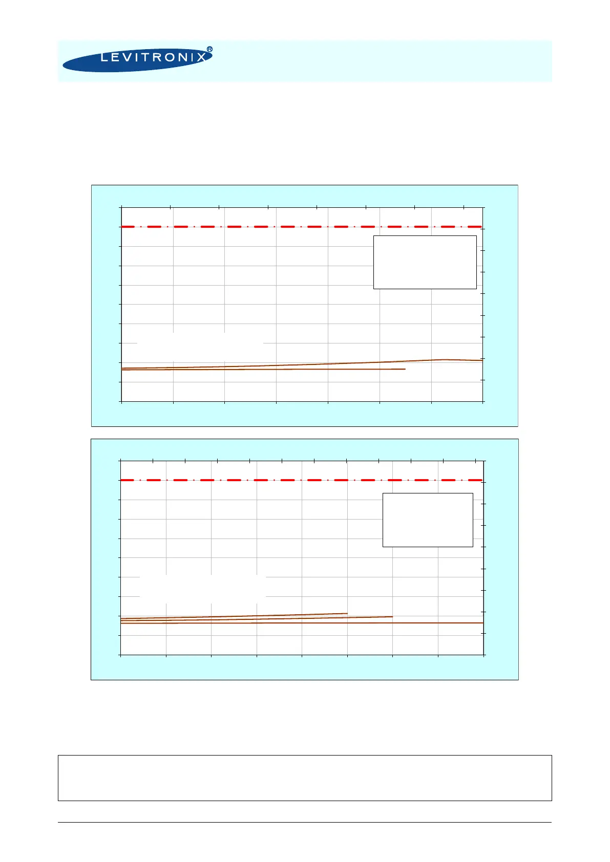
3.4.2 Controller Temperature
Depending on the ambient temperature and the placement of the controller additional cooling may be
required (see Figure 24). To improve cooling of the controller, place the device into a moving air stream. If
the controller is mounted in a compact area or adjacent to additional heat sources (e.g. a 2
nd
controller)
ensure that there is sufficient ventilation.
Figure 24: Temperature curves of controller LPC-2000 vs. flow and speed
(For pumping with pump head LPP-2000.6/7 and motor LPM-2000.2)
The above curves are measurements of the controller temperature at 25°C ambient. Equation (Eq. 2) shows
how to calculate the controller temperature for at other ambient temperatures based on this curve.
etemperatur AmbientT
etemperatur ControllerT
CTCTTTT
A
C
AACAC
24 Figure see
)25()25()(
00
77
87
97
107
117
127
137
147
157
167
0 5 10 15 20 25 30 35
25
30
35
40
45
50
55
60
65
70
75
0 20 40 60 80 100 120 140
[°F]
[gpm]
[
0
C]
[lpm]
Ambient temp. = 25 C
Specific gravity = 1 g/cm
3
Viscosity = 0.7 cP
PWM Drive = 4.38 kHz
PWM Bearing = 17.51 kHz
Fan: Temp. Controlled
Absolute Temperature Limit
77
87
97
107
117
127
137
147
157
167
0 2 4 6 8 10 12 14 16 18 20 22
25
30
35
40
45
50
55
60
65
70
75
0 10 20 30 40 50 60 70 80
[°F]
[gpm]
[
0
C]
[lpm]
Ambient temp. = 25 C
Specific gravity = 1 g/cm
3
Viscosity = 0.7 cP
PWM Drive = 4.38 kHz
PWM Bearing = 17.51 kHz
Fan: Temp. Controlled
Absolute Temperature Limit
High-Flow System
Pump Head LPP-2000.6
High-Pressure System
Pump Head LPP-2000.7