4.1.5 Installation Extended Controller LPC-4000.2 with PLC Interface
To operate the pump system with a PLC, a minimum set of two digital inputs and one analog input is needed.
The digital and analog outputs can be used to monitor the pump status and operating parameters.
The analog inputs and outputs are not galvanic isolated from the
controller electronics. To avoid ground loops and mal-functions, use
floating analog signals.
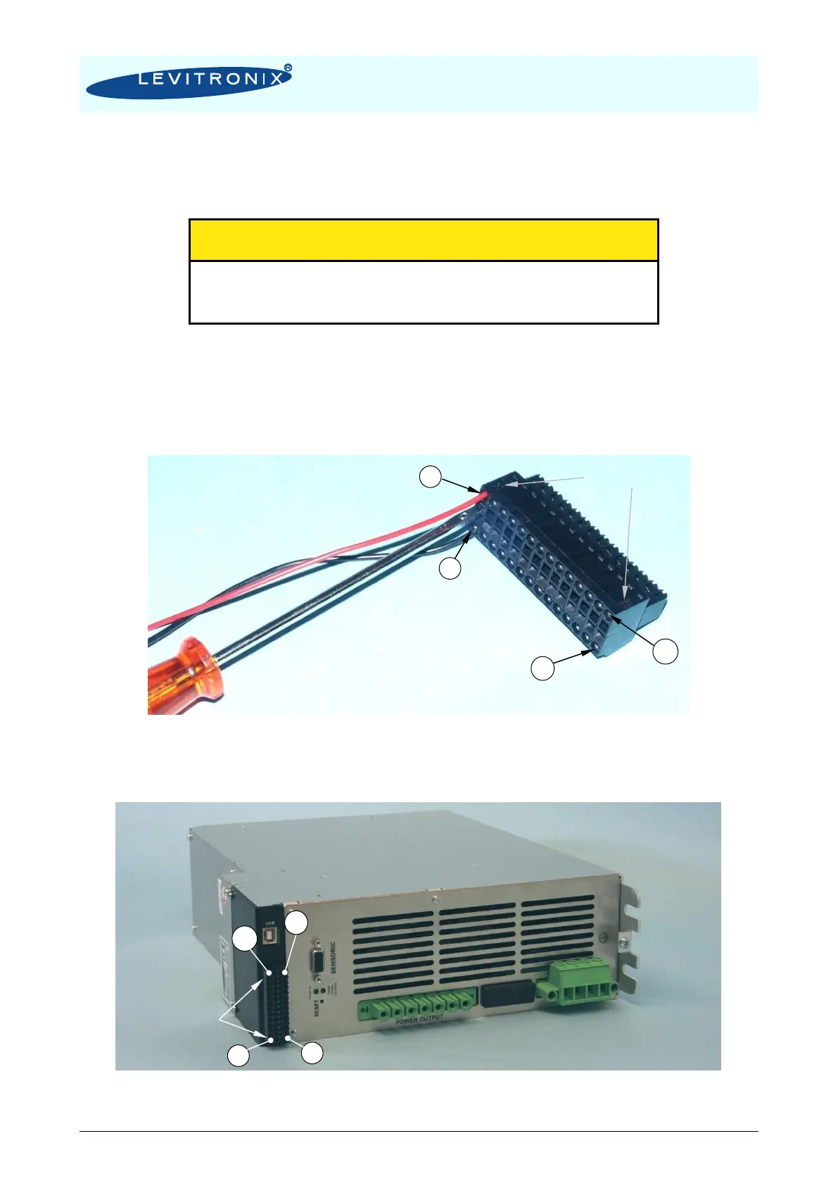
1. Detach the PLC connector from the controller
2. Connect the designated wires of a cable the pins of the detached connector according to
Table 13. Assignment and functions of the I/Os can be changed with the controller firmware
version (refer to according firmware documentation).
3. Connect the PLC connector (Figure 28) to the controller.
Figure 28: PLC connector
- Delivered with controller LPC-4000.2
- Supplier: Weidmüller
- Connector Type: B2L 3.5/28 SN BK BX
Figure 29: Mounted PLC connector and pin numbering