User Manual for BPS-4000
www.levitronix.com
PL-4016-00, Rev11, DCO# 18-057
4.3 Mechanical Installation of the Controller
▪ The controller can be fixed with four screws (for example M7) on the Controller feet (see
Figure 13)
▪ If no forced air-cooling is used, mount the controller in upright position and assure that the
heat of the controller can dissipate. Avoid mounting the controller in a cabinet were heat is
stagnated and accumulated.
Hazardous voltage may be present.
In order to avoiding fluid spills shorting mains or other voltages within
the controller, place the controller in a spill protected electronic cabinet.
If explosive flammable gases are present, place the controller in an
explosion-proof cabinet.
Do not under any circumstances open the controller. Levitronix does
not assume responsibility for any damage, which occurs under such
circumstances.
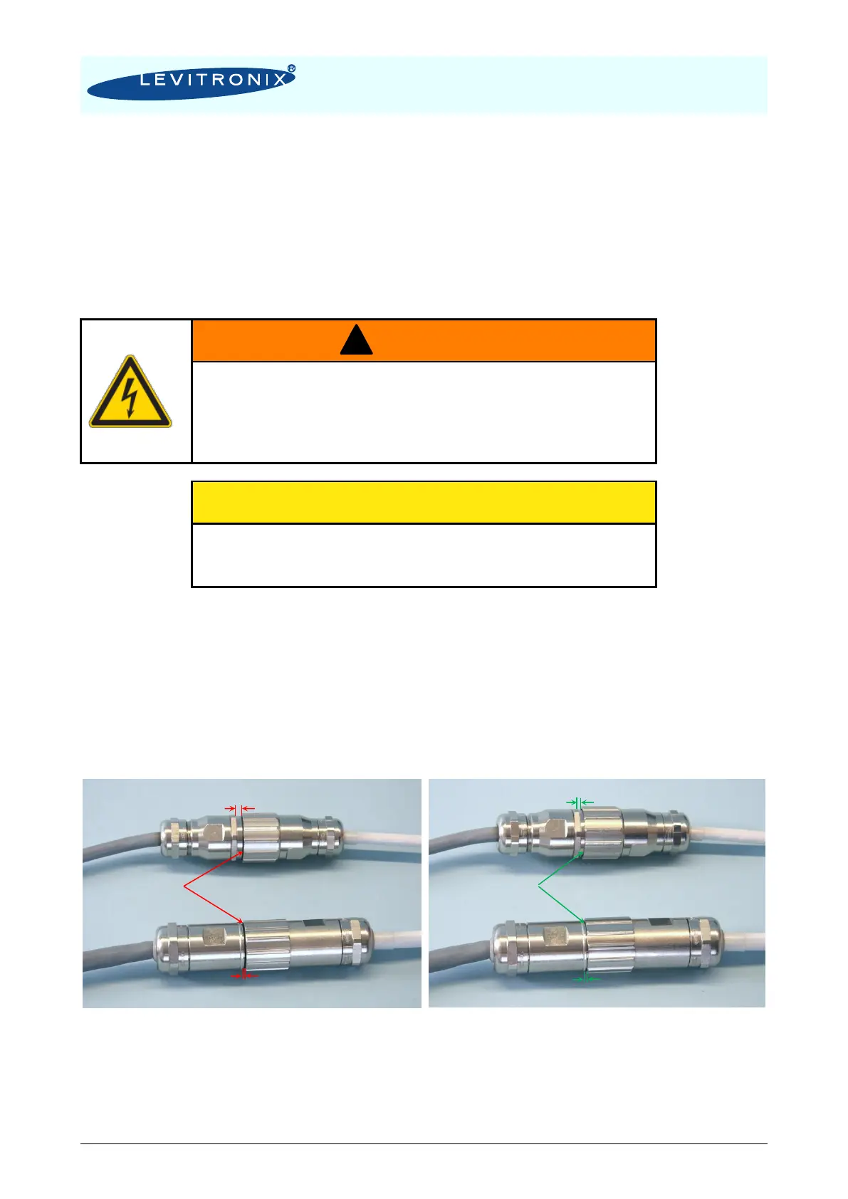
4.4 Mechanical Installation of Adaptor/Extension Cables
For connecting the motor to the controller the adaptor cables MCAP-4000.x (for power cable) and MCAS-
600.x (for sensor cable) shall be used (see Table 3 for adaptor cables). For the cables which use an M23
threaded metallic Hummel connector type, check the connection according to the following pictures:
Figure 32: Wrong and correct Hummel connector type assembly