Note: This task requires a flathead screwdriver.
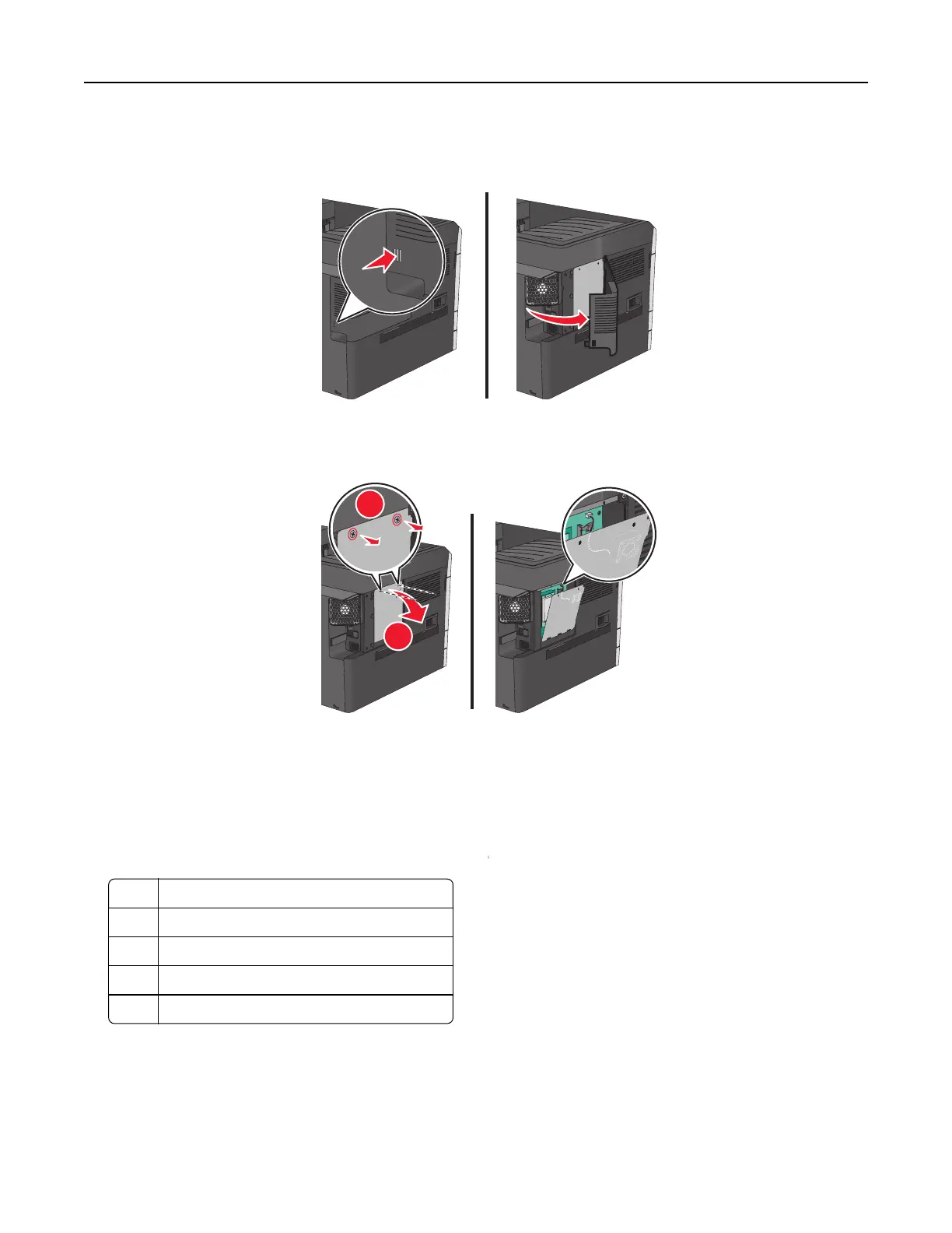
1 Remove the cover.
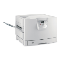
2 Turn the screws on the metal panel counterclockwise to remove them, and then pull the panel down.
Note: Remove the two screws emphasized in the illustration.
1
2
Note: Do not unplug the fan cable unless necessary.
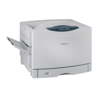
3 Use the following illustration to locate the appropriate connectors.
Warning—Potential Damage: System board electronic components are easily damaged by static electricity.
Touch something metal on the printer before touching any system board electronic components or connectors.
1 Fan cable connector
2 Memory card connector
3 Firmware and flash memory card connectors
4 ISP connector
5 Hard disk connector
4 Reattach the metal panel.
Note: Make sure the fan cable is plugged to its connector before reattaching the metal panel.
Additional printer setup 22