Installation
11
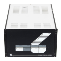
Fig. 2.3 NT 20 adapter
0,2 m
25-way
Sub-D
2x 10-way Phoenix
0 to 10
Coding at
pins 4 and 7
11 to 20
Coding at pins
11 and 20
Turbo.Drive TD20
classic
NT 20
Pin Designation Pin Designation
1 Remote (Input) 2 Remote +
2 Start[H] (Input) 6 Start +
3 Stop[L] (Input) 4 Stop +
4 Control GND 1,3,5 Remote -, Start -, Stop -
5 Supply GND 9 GND
6 24 V DC, max. 80 mA 10 + 15 V (Voltage changed
to + 24 V DC)
7 Analog output (not implemented) not connected
8 Error (Relay) (n.o.) 13 Error (Relay) (n.o.)
9 Error (Relay) com. 14 Error (Relay) com.
10 Normal (Relay) (n.o.) 11 Normal (Relay) (n.o.)
11 Normal (Relay) com. 12 Normal (Relay) com.
12 Pump rotates (Relay) (n.o.) not connected
13 Pump rotates (Relay) com. not connected
14 Option1 (Input) (not implemented) not connected
15 Option 2 (Input) (not implemented) not connected
16 Acceleration (Relay) com. 16 Run-up (Relay) com.
17 Analog GND (not implemented) not connected
18 Option relay 3 (n.o.) 18 Option (Relay) (n.o.)
19 Option relay 3 com. 19 Option (Relay) com.
20 Option relay 3 (n.c.). 20 Option (Relay) (n.c.).
21 Error (Relay) (n.c.) 15 Error (Relay) (n.c.)
22 Option 3 (Input) not connected
23 Acceleration (Relay) (n.o.) 17 Run-up (Relay) (n.o.)
24 Speed (Analog input) not connected
(not implemented)
Housing Connected with Cable shielding
Housing ground (PE)
Pins 7 and 8 Heating
not connected
0.2 m
Note
If optional relay 3 shall operate in the
same way as for the NT 20, then set
parameter 318 to 5 (default).
 Loading...