Home
LG
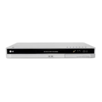
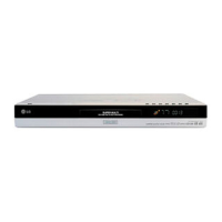
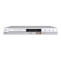
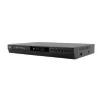
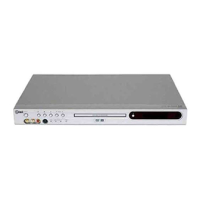
DVD Recorder
DR1F9H
LG DR1F9H User Manual
4
of 1
of 1 rating
146 pages
Give review
Manual
Specs
To Next Page
To Next Page
To Previous Page
To Previous Page
Loading...
3-16
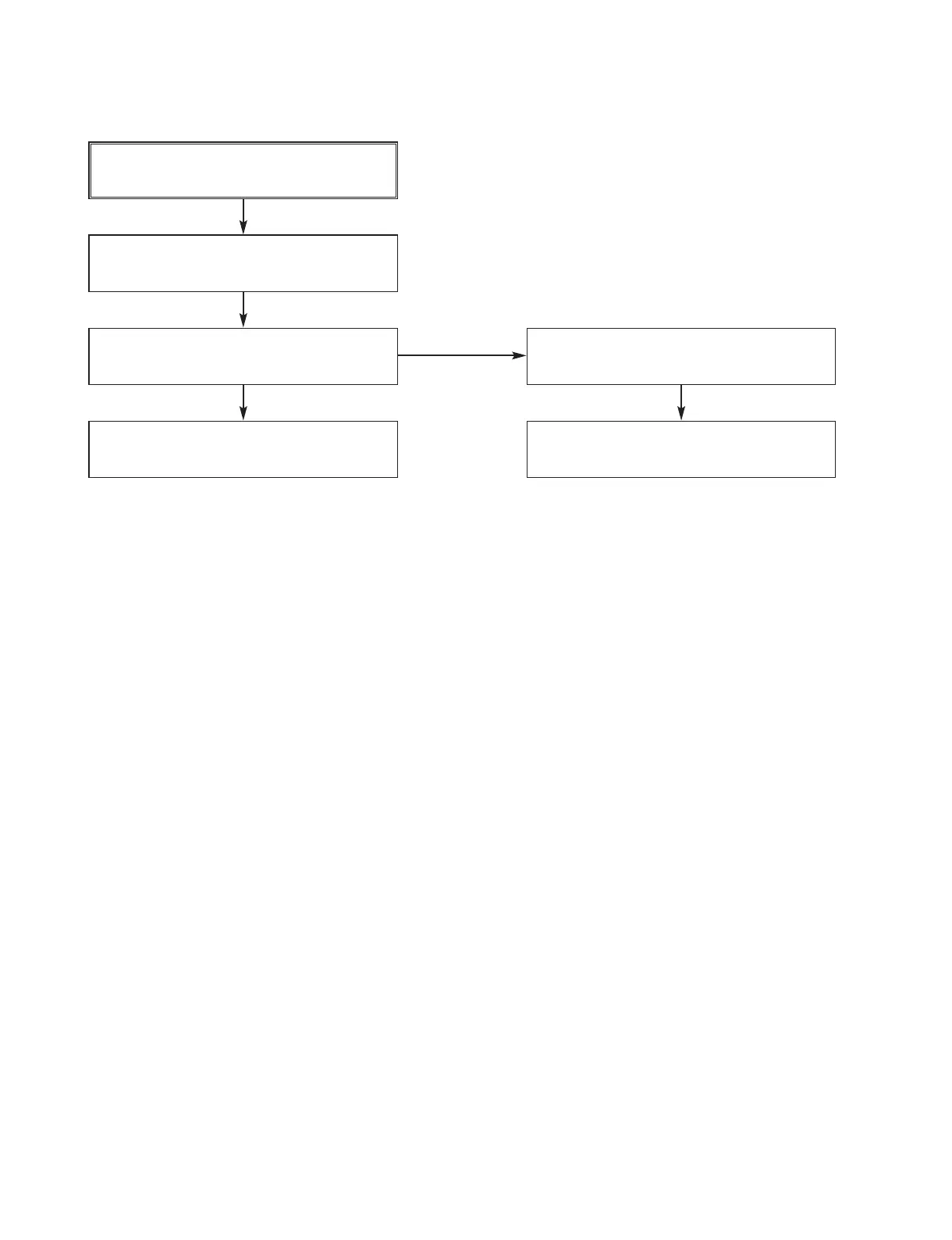
9. NO RGB / COMPONENT VIDEO SIGNAL
WHEN PLA
Y
DISC
L1408, L1427, L1428 :Is there a signal ?
PVM01 pin 2, 6, 10 : Is there a signal ?
YES
IC802 pin 18, 21, 24 : Is there a signal ?
YES
CHECK IC802 pin 1,16 (5.2V)
NO
Replace IC802
CHECK SW801 status & SW801 pin 2
(RGB_SEL
”
H
”
)
YES
YES
30
32
Table of Contents
Section 1 Summary
3
Table of Contents
3
Product Safety Servicing Guidelines for Video Products
4
Servicing Precautions
5
General Servicing Precautions
5
Insulation Checking Prodedure
5
Electrostatically Sensitive Devices
5
Service Information for Eeprom IC Setting
6
Flash Upgrade
7
Loader Upgrade
9
Specifications
11
Section 2 Cabinet & Main Chassis
12
Cabinet and Main Frame Section
13
Exploded Views
13
Deck Mechanism Section(RS-01A)
14
Packing Accessory Section
15
Section 3 Electrical
16
Electrical Troubleshooting Guide
17
Power Supply on Smps Board
17
Vdr Part
17
Power Supply on I/O Board
19
Disc Not Recognized
26
System Circuit Part
26
When Playing Disc, no Audio Output
27
Optical / Digital Output
28
Tuner Audio Output
29
External Audio Input
30
Rgb / Component Video Signal When Play Disc
31
Composite / S-Video Signal When Play Disc
32
Tv, External Input Video Signal
33
DV(Ieee 1394) Input (Video/Audio) Signal
34
Block Diagrams
36
Power Block Diagram
36
Main Power Block Diagram
37
Video in Block Diagram
38
Video out Block Diagram
39
Audio in Block Diagram
40
Audio out Block Diagram
41
System Main Block Diagram
42
I/O Μ-COM BLOCK DIAGRAM
43
Scart Block Diagram(Scart Model Only)
44
Hdmi Block Diagram (Hdmi Model Only)
45
Memory Block Diagram (Memory Slot Model Only)
46
Circuit Diagrams
47
Main Power Circuit Diagram
48
Mpeg Circuit Diagram
49
A.latch/Flash/Ddr Circuit Diagram
50
Loader/DV Circuit Diagram
51
I/O Μ-COM CIRCUIT DIAGRAM
52
Tuner/Mpx/Adc/Dac/Jack Circuit Diagram
53
Decoder Circuit Diagram
54
Hdmi Circuit Diagram
55
Timer Circuit Diagram
56
Key Circuit Diagram
57
Waveforms
58
Circuit Voltage Chart
59
Main P.C.board(Top Side)
62
Printed Circuit Diagrams
62
Main P.C.board(Bottom Side)
63
Hdmi P.C.board(Optional Parts)
64
I/O P.C.board
64
Key P.C.board
65
Timer P.C.board
65
Power P.C.board
66
Section 4 Rs-01A Loader Part
68
Electrical Troubleshooting Guide
69
Recording Layer
83
The Difference of DVD-R/Rw, DVD+R/Rw Discs and DVD-Rom
83
Disc Materials
84
Disc Specification
84
Organization of the Inner Drive Area, Outer Drive Area, Lead-In Zone and Lead-Out Zone
88
Alpc Measurement System
91
Alpc Program
91
How to Use Test Tool
91
Execute Alpc Program
92
Optical Power Setting
94
Confirm Optical Power Setting Parameter
95
Optical Power Setting Parameter Range
96
Attachment. Optical Power Measurement
97
Block Diagram of the Pick-Up(Lpc-812R)
98
Internal Structure of the Pick-Up
98
Pick up Pin Assignment
99
Signal Detection of the P/U
100
Alpc (Automatic Laser Power Control) Circuit
101
Description of Circuit
101
Focus/Tracking/Sled Servo Circuit
102
Spindle Servo Circuit
104
Lic121 (An22113A) : Fep(Rf) Analog Signal Processor
105
Major IC Internal Block Diagram
105
Ic301 (Bd7956Fs) : CD-Rom/DVD-Rom 7Ch Power Driver
108
Circuit Diagrams
110
Dsp Circuit Diagram
110
Rf Circuit Diagram
111
Drive Circuit Diagram
112
Circuit Voltage Chart
113
Main P.C.board(Top View)
114
Printed Circuit Diagrams
114
Main P.C.board(Bottom View)
115
Other manuals for LG DR1F9H
Specifications
2 pages
4
Based on 1 rating
Ask a question
Give review
Questions and Answers:
Need help?
Do you have a question about the LG DR1F9H and is the answer not in the manual?
Ask a question
LG DR1F9H Specifications
General
Brand
LG
Model
DR1F9H
Category
DVD Recorder
Language
English
Related product manuals
LG DR165
49 pages
LG DR197
50 pages
LG DR275
47 pages
LG DR265
48 pages
LG DR788
151 pages
LG DR4912
64 pages
LG DR7400
48 pages
LG DRT389H
40 pages
LG DR275-W
47 pages
LG DR265-P1
47 pages
LG SP80
6 pages
LG LRY-517
64 pages
 Loading...