• Design pressure is 551 psig.
• All dimensions in inches. Tolerance ±1/4 inch.
• Images are not to scale.
REFRIGERANT PIPING DESIGN
LG Engineered Multi F MAX Y-Branch Kit
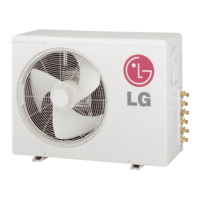
The LG supplied Y-Branch Kit PMBL5620 MUST be used when two
branch distribution units are connected on one Multi F MAX system.
Field-supplied fittings are not permitted. Each Y-Branch kit comes
with two (2) Y-branches (one for the liquid line and one for the vapor
line) and insulation covers.
Y-branches may be installed in horizontal or vertical configurations.
When installed vertically, position the Y-branch so the straight-
through leg is ±3° of plumb. When installed horizontally, position the
Y-branch so the take-off leg is level and shares the same horizontal
plane as the straight-through leg ±10° rotation.
Y-branches must be properly installed following instructions in the
applicable LG manual. Y-branches should always be installed with
the single port facing the outdoor unit and the two-port end facing
the branch distribution units. Do not install Y-branches backwards
as refrigerant flow cannot make U-turns. The Y-branch kit must be
located at least three (3) feet from the outdoor unit. Provide
a minimum of 20 inches between a Y-branch and the branch
distribution unit.
It is recommended that when a Y-branch is located in a pipe chase
or other concealed space, access doors should be provided for
inspection access.
The equivalent pipe length of each Y-branch (1.6′) must be added to
the main pipe segment entered into LATS piping design software.
Figure 257:Y-Branch Connections.
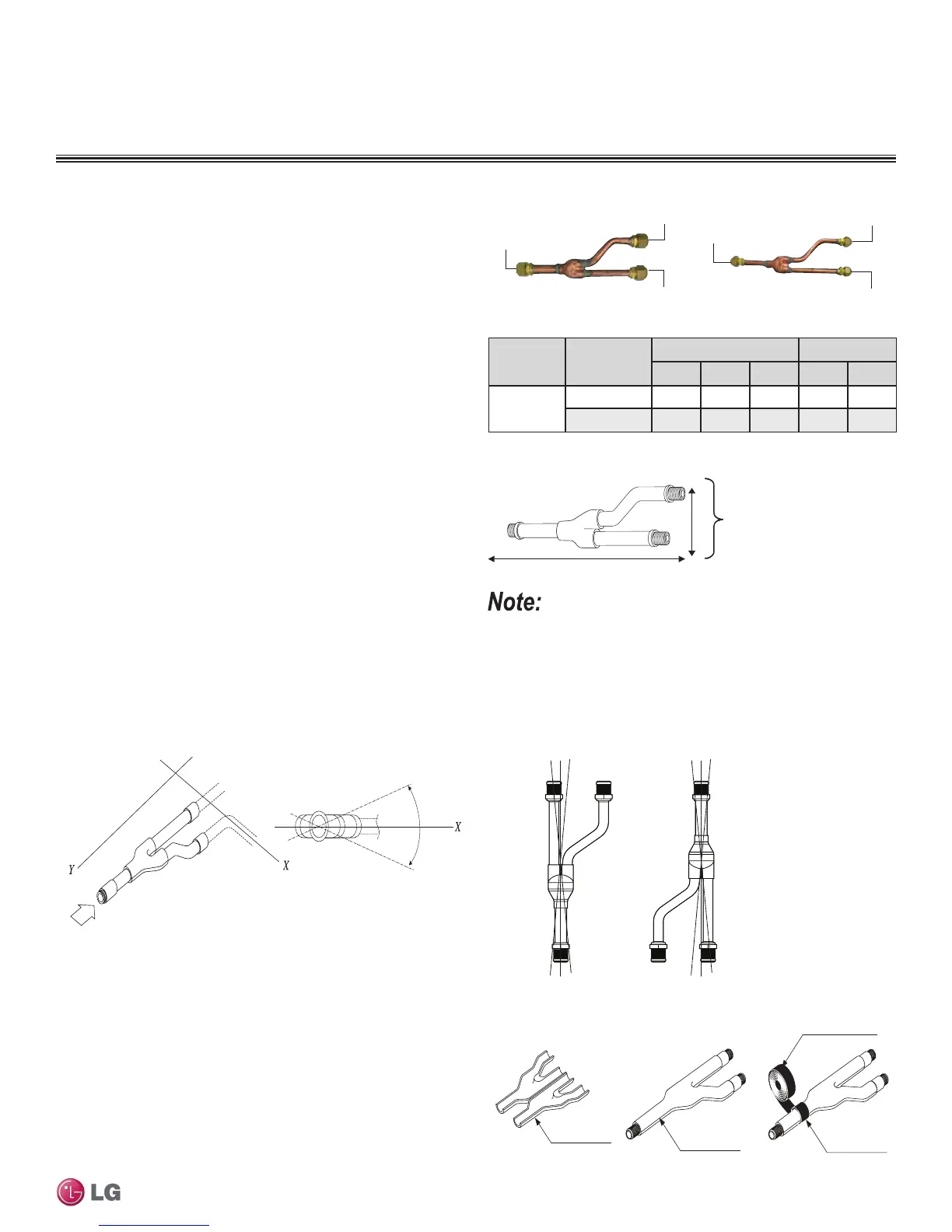
Figure 258:Y-Branch Dimensions Diagram.
Figure 259:Horizontal Conguration End View.
Multi F MAX Y-Branch Kit PMBL5620
Table 110:Y-Branch Connection Diameters.
Model
Y-Branch
Type
Port Identier (inch) Dimensions
1 2 3 X Y
PMBL5620
Liquid 3/8 3/8 3/8 13.80 3.24
Vapor 3/4 3/4 3/4 12.48 3.02
To Branch Distribution Unit Ø3/4
Ø3/4
To Outdoor Unit
Ø3/4
Ø3/8
Ø3/8
To Outdoor Unit
To Branch Distribution Unit Ø3/8
Y-Branch Kit Insulation
Each Y-branch kit comes with clam-shell type peel-and-stick insula-
tion jackets molded to fit the Y-branch fittings—one for the liquid
line, one for the vapor line.
• Check the fit of the Y-branch clam-shell insulation jacket after the
Y-branch is installed.
• Mark the pipe where the insulation jacket ends.
• Remove the jacket.
• Install field-provided insulation on the pipes first.
• Peel the adhesive glue protector slip and install the clam-shell
jacket over the fitting
Figure 260:Y-branch Installation Alignment Specication.
Viewed from A in direction of arrow
Horizontal
plane
Within 10°
Configuration
Within ± 3°Within ± 3°
Vertical Down
Configuration
Liquid and Gas
Pipe Joints
Y-Branch Kit Insulation
Insulation for
Field-Installed Piping
Field-Supplied Insulation Tape
A = To Outdoor Unit
B = To Branch
Distribution Unit
Figure 261:Y-branch Insulation Detail.
Due to our policy of continuous product innovation, some specications may change without notication.
©LG Electronics U.S.A., Inc., Englewood Cliffs, NJ. All rights reserved. “LG” is a registered trademark of LG Corp.
DESIGN & PRACTICES | 195
Refrigerant Piping Design and Best Practices

 Loading...