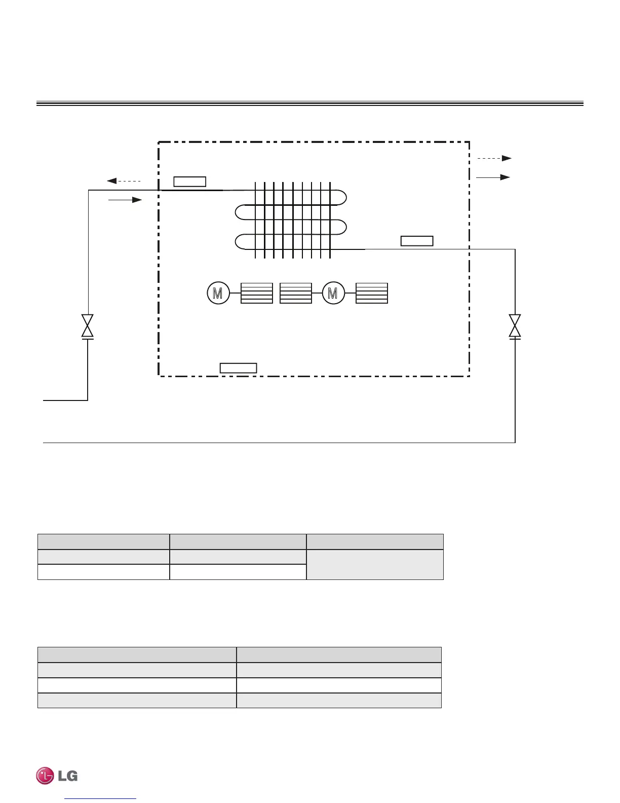
Figure 127:LMDN126HV and LMDN186HV Refrigerant Flow Diagram.
DUCT (LOW STATIC) INDOOR UNITS
Refrigerant Flow Diagrams
Table 49: Multi F Ceiling-Concealed Duct (Low Static) LMDN126HV and LMDN186HV Indoor Unit Refrigerant
Pipe Connection Port Diameters.
Model No. Vapor (inch) Liquid (inch)
LMDN126HV Ø3/8
Ø1/4
LMDN186HV Ø1/2
Table 50: Multi F Ceiling-Concealed Duct (Low Static) LMDN126HV and LMDN186HV Indoor Unit Thermistor Details.
Description (Based on Cooling Mode) PCB Connector
Indoor Air Temperature Thermistor CN-ROOM
Evaporator Inlet Temperature Thermistor CN-PIPE/IN
Evaporator Outlet Temperature Thermistor CN-PIPE/OUT
Indoor Unit
: Cooling
: Heating
MM
Sirocco Fan
Indoor Air
Temperature
Thermistor
Evaporator
Outlet
Temperature
Thermistor
Evaporator
Inlet
Temperature
Thermistor
DUCT (LOW STATIC) | 99
Ceiling-Concealed Duct (Low Static)
Due to our policy of continuous product innovation, some specications may change without notication.
©LG Electronics U.S.A., Inc., Englewood Cliffs, NJ. All rights reserved. “LG” is a registered trademark of LG Corp.

 Loading...