Chapter 3 - Insatallation Procedure 7200 Series UPS User Manual
Connecting the UPS power cables Single Module and 1+1 Parallel System
document in response to "powersure ups"
Page 3-10
Issue 6
(03/98)
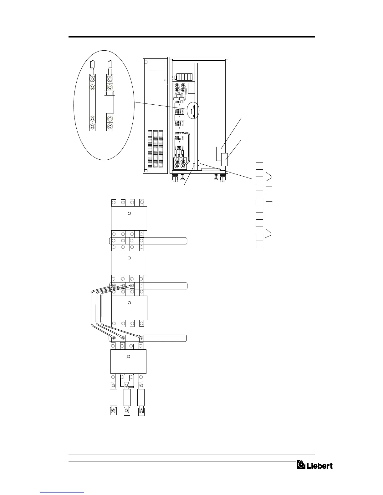
Figure 3-E . Power and control cable connections
1
4
5
6
8
9
10
11
12
7
2
3
Battery Power
connections
Cable < D >
Safety Earth
Output
Connections
(To load)
Cable < C >
Input connections for
split bypass system
(From Mains a.c. supply)
Cable < B >
UPS Rectifier Input connections
(From Mains a.c. supply)
Cable < A >
These linkes must
be removed for split
bypass
+
-
R
T
S
Z2
N
K1
R
T
S
Z1
N
F13
+
_
X 3 - Cables < E > and < H >
Q1
Q2
Q3
Q4
U2 V2 W2 N2
U3 V3 W3 N3
AS400/alarms
connections
Cable < G >
Communication
connections
Cable < F >
Batt.
temp.
E.P.O.
Common
Batt.CB Aux. contact
Batt. CB trip
U1 V1 W1
 Loading...